|

|

|

|

|

|
| Home | Manuals | Supplies | Search | Consult | Contact | Testing | Service |
|
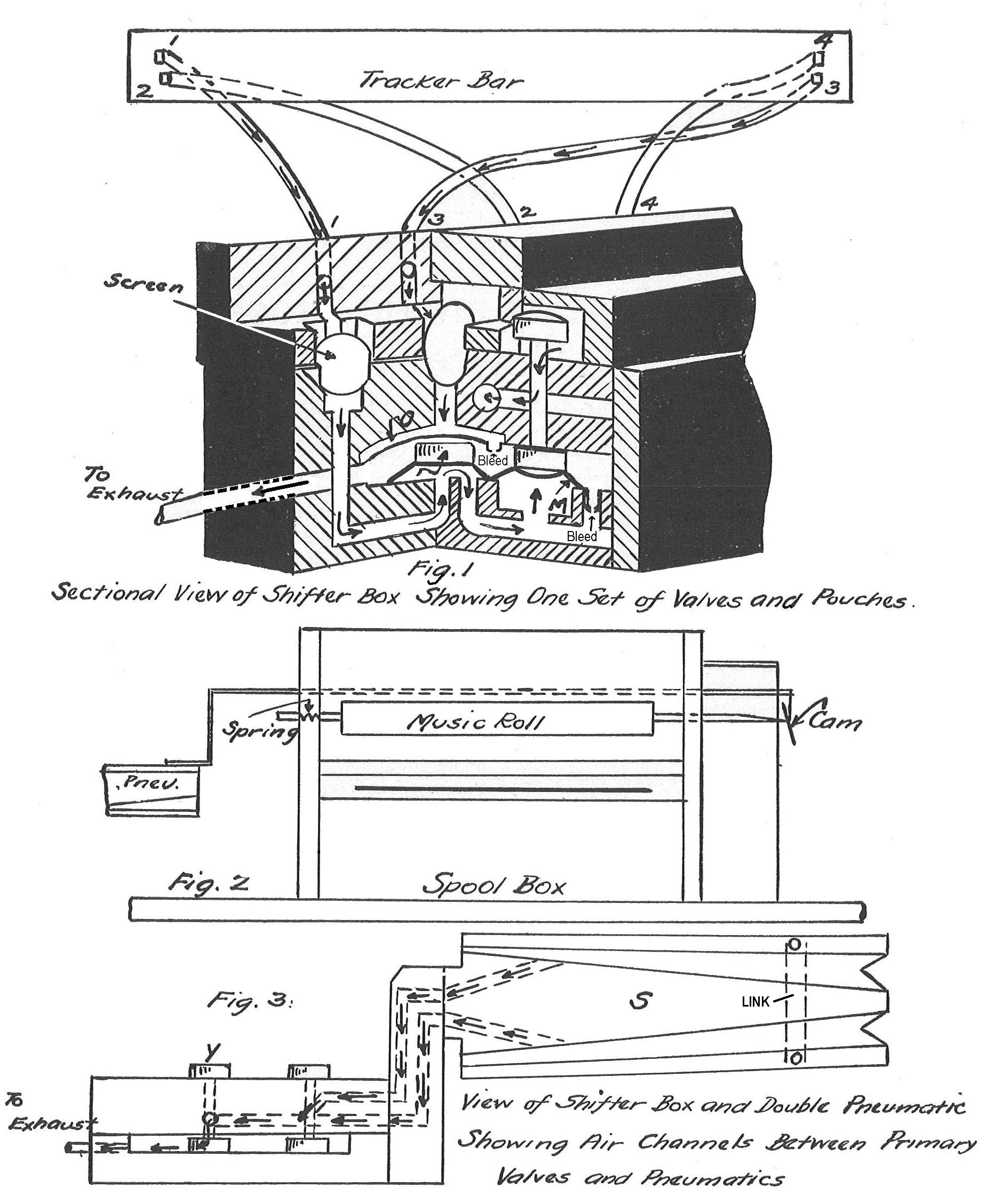
A, B, C, D Metal Tubes leading from the Tracker Bar. E — Cap over sieves. F — Pouch under Front Valve. G — Front Valve. H — Channel under Pouch. I — Gauze Sieves or Dust Arresters J and J-1 — Channels to Pneumatics. (J and K-1 — Channels are separate and distinct, channel J operating upper pneumatic connects with pneumatic K. J-1 operating lower pneumatic connects with pneumatic K-1.) |
K and K-1 — Shifter Pneumatics. (Separate Pneumatics) L — Screws securing sieve Cover. M — Governor Vent. N — Balance Spring. O — Back Valve. P — Cut-off Pouch. Q — Pouch under Back Valve. R — Exhaust Chamber. S — Nipple to connect with Top Action. T — Cap over front valves. U — Air inlet for front valves. V — Hinge for connecting wire. |
|
The purpose of the pneumatic tracking device is to keep the roll of music running true over the tracker bar so that the perforations in the music roll will be in perfect alignment with their corresponding-holes in the tracker bar. At times the music roll on all players has a tendency to work over to the right or left and if this is not corrected instantly, it will result in a discord because the perforations in the music roll will then open the wrong holes in the tracker bar, thus causing the wrong notes to play. We will first explain the exterior working of the tracking device the action that can be seen. Then we will explain the operation of the valves and pouches that are inside the shifter box.

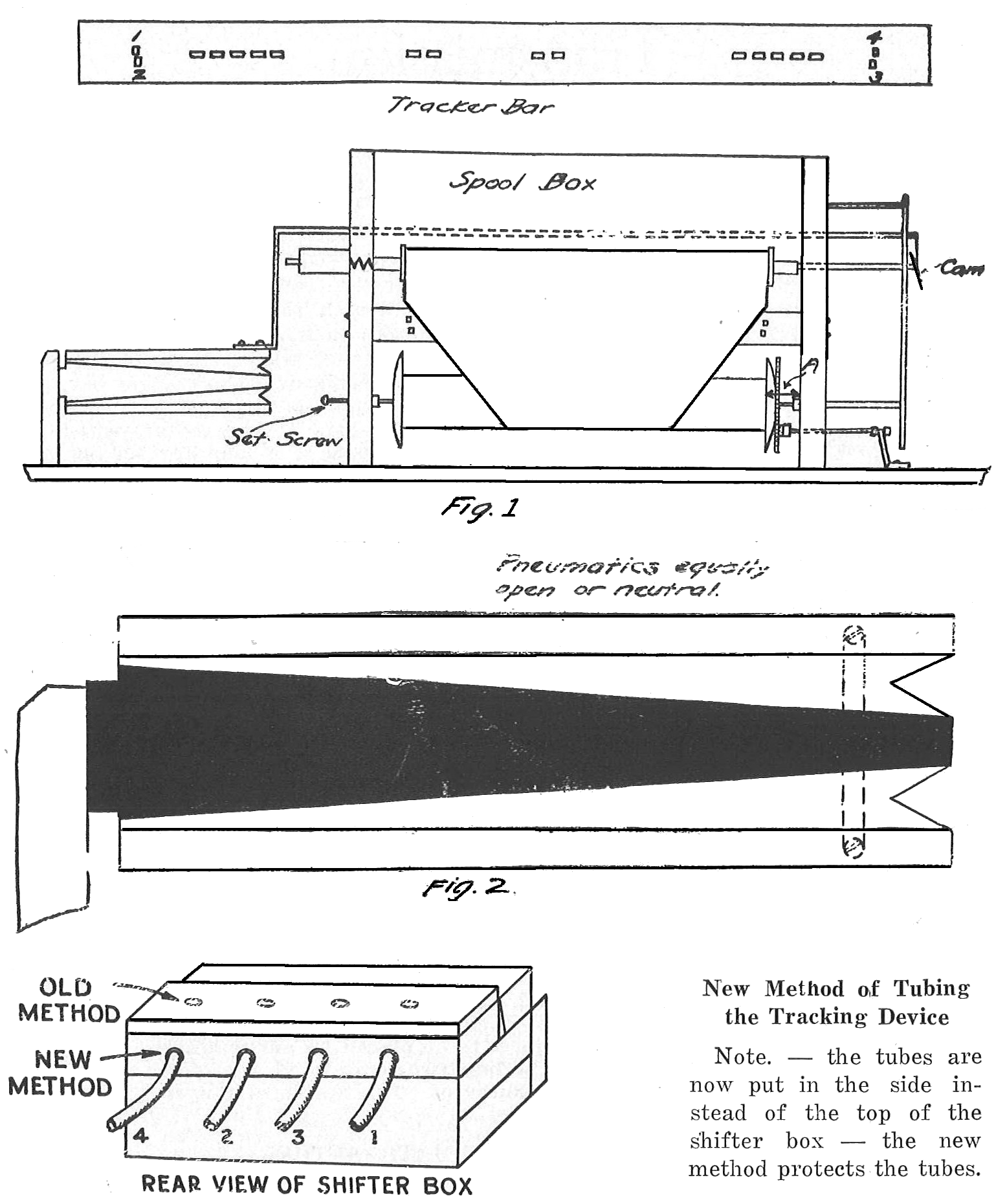
Glance at the cross-sectional view of the tracking device, illustrated by figure 3. You will see that it is equipped with a double pneumatic; the two pneumatics are linked together part way open so as to allow one pneumatic to open entirely while the opposite pneumatic collapses entirely. There is one stationary leaf for the two pneumatics, illustrated by S, figure 3. The upward and downward movement of this double pneumatic operates, thru connections, a crescent shaped piece of metal known as a "cam." This cam is located to the right of the music box, as indicated in figure 2. When each of the pneumatics of the double pneumatic is open an equal distance, the end of the shaft which holds the right end of the music roll rests against the center of this cam, as illustrated in figure 2. You will see in the sketch that the cam is set at an angle of about ten degrees. Therefore, when the cam moves downward it presses against the shaft that holds the roll, and the roll is pushed to the left. If the cam were set perpendicularly this would not be possible. There is a spring in the plunger bearing which holds the left end of the music roll, so that when the music roll moves to the left it does so against spring pressure. When the cam moves upward the pressure that it exerts is lessened, which permits the spring pressure in the plunger bearing to force the roll to the right and the roll resumes its proper position.
Probably much of the confusion or perplexity regarding the operation of the shifter device is due to lack of understanding the reason for the existence of the four extra holes in the tracker bar. (Two on each side of the regular holes, indicated by 1 - 4 and 2 - 3, figure 1.) Let us emphasize that the upper and outside holes 1 and 4 are for the purpose of controlling rolls of a standard width or wider, and the lower and inside holes 2 and 3 are for rolls of a width narrower than the standard. These holes are connected to the shifter box by tubes indicated in figure 1. The shifter box contains two complete sets of valves and pouches. In order that this article may not become complicated, we will explain only the operation for one set of valves, and one set of pouches. Please understand that the operation of the second set is identically the same as the one which we are about to describe, the only difference being that the roll is moved in the opposite direction when the other set of valves operates. Place a roll of music of standard width in the spool box and start to pump on the treadles. You will see that the edge of the paper entirely covers the four extra holes in the tracker bar. When in this position the two pneumatics are connected with the exhaust, as illustrated in figure 3, and the air is drawn out of each of the pneumatics as indicated by arrows in figure 3. Figure 3 illustrates the two valves closed and consequently each of the pneumatics is open equally because the air is being exhausted equally from each. The primary valve Y, figures 1 and 3, controls the air passage of the lower pneumatic. The other valves control the passage to the upper pneumatic. As explained above, when valve Y is closed it connects the pneumatic with the exhaust. When it is raised it connects the pneumatic with tho outside air. For a more detailed explanation of what is going on inside of the shifter box, and how the valves are able to sense that the holes in the trackerbar are covered, read "What's Happening Inside".
Now move the paper to the right just far enough to uncover hole 1. The outside air rushes into hole 1 and down thru tube 1 to the shifter box. The passage of this air is indicated by small arrows. (The screen indicated in figure 1 is merely a wire mesh which prevents dust from entering the valve box.) The air flows up under cut-off pouch P, forcing it up, which permits the air to flow round thru the channels and reach a position under pouch M. The passage of this air is indicated by arrows. The pressure of air from underneath pouch M in turn raises valve Y and connects the bottom pneumatic with the outside air. The air flows down thru the channels opened by the raising of valve Y, indicated by small arrows, and inflates the bottom pneumatic. (In the sketch it might seem that the housing that protects valve Y is air tight -this is not so.) The air filters in around this housing so that the pneumatic may be inflated when the valve is raised. The housing is placed over the valve so that it may be protected. The top pneumatic is still connected with the exhaust, which makes it the weaker. The outside air pressure then causes the lower pneumatic to inflate and the upper pneumatic to collapse entirely. (Remember that the upper pneumatic is connected with the exhaust.) As the bottom pneumatic inflates it forces the cam down, which pushes roll to left.
Now we will take up the operation when a roll of narrower width than the standard width is used. In this case the two upper holes would be entirely uncovered and the air would continue to flow down thru each of these, raising the two primary valves and thereby connecting the two pneumatics with the outside air. In this case the two pneumatics remain neutral, which will keep the roll of music running true over the tracker bar. But if the roll should shift a trifle to the left, hole 3 would be uncovered. The air would then rush down thru tube 3, indicated by arrows, and push down on pouch O figure 1, which in turn would force cut-off pouch P to close. The closing of the cut-off pouch P closes the air channel between tube 1 and pouch M. This permits primary valve Y to settle back to its former position, closing this pneumatic to the outside air. Consequently the lower pneumatic becomes connected with the exhaust and the upper pneumatic is inflated, the cam is raised and pushes the roll back to its proper position.
 To test the pneumatic tracking device, first place the music roll over the tracker bar so that the blank paper covers the 88 holes in the tracker bar, but does not cover the four shifter holes -then pump on the treadles. When this position, that is when the four shifter holes are uncovered, the tracking device pneumatics should be equally open or neutral, as illustrated in figure 2. Then place your finger over one of the two lower tracker holes, leaving the other three uncovered. When in this position, one of the pneumatics should collapse. Then make the same test with the opposite lower shifter hole and see if the other pneumatic collapses. Next place your thumbs over the two lower holes, and also over one of the upper holes, only leaving one shifter hole open. In this position, one of the pneumatics should collapse. Then repeat the same operation with the opposite hole, and watch to see if the other pneumatic collapses. If, when making these tests, you should find that one of the pneumatics collapses, but the other does not, tighten all the screws in the tracking device, to make sure that there is no leakage. If it still does not work, examine the tubes and joints to see that there is no leakage there. If, after these tests have been made, one of the pneumatics does not operate, either the tubes are clogged, or something is wrong with one of the pouches or valves.
To set the tracking device, first see that the two pneumatics are centered. That is, that each of the pneumatics is equally open or neutral, as illustrated in figure 2. Then see that all the wire connections leading from the pneumatic to the cam are adjusted so that the end of the upper shaft which holds the music roll in place, touches the center of the cam, as illustrated in figure 1. If the cam is not centered, it may be adjusted by loosening the set screw on top of the cam.
Next adjust the take-up spool, to make sure that this is set properly. There should be an equal distance from the inside of the flange to the inside of the spool box on either side of the spool box, as illustrated in figure 1. There is a set screw on the left-hand side of the spool box for the purpose of adjusting the take-up spool. Also see that the brake on the take-up spool is properly adjusted so that the take-up spool does not run too freely or is binding too much on the re-roll. After this has been done, line up the music roll with the take-up spool. If, as stated above, the music roll does not line perfectly with the take-up spool, the position of the music roll may be corrected by adjusting the cam, but be careful not to get same out of center or for minor adjustments reset at No. 14 collar on shifter rod, at left side of spool box. When the music roll is lined on the take-up spool, there should be a margin of 1/32 of an inch on either side (between the paper and the inside of the flange) which allows for the pneumatic tracking device to operate. |

![]() ..To
The Top of this Page . . . . . . . . . . .
..To
The Top of this Page . . . . . . . . . . . ![]() ..To The HOME Page
..To The HOME Page
|
Since "Player-Care" is an internet business, I prefer that we correspond via E-Mail (click here to fill out the 'Request Form'). However, if I'm not in the middle of some other activity, you can reach me at 732-840-8787. But please understand that during the hours from 8AM-5PM EST (Mon-Sat), I'm generally quite busy. So, I probably won't answer the phone. If you get the answering machine, please leave a detailed message stating the reason for your call. Also, repeat your name and phone number clearly and distinctly. By necessity, I prioritize everything in my life. And, if you call and just leave your name and number, and ask me to call you back, it might be a day or two before I return your call. Why? Because I don't know why you want me to call and I might not be prepared to assist you in an effective and efficient manner. If you leave me an E-Mail address (which I prefer), spell it out phonetically. The more you do to help me, the more I can help you in return. Don't rush. You have four minutes to record your message. |
|
407 19th Ave, Brick, NJ, 08724 Phone Number 732-840-8787 (Voicemail Only, No Texts) |
