
|
|
|
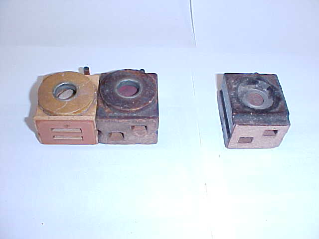 |
PHOTO B 1 Valve Transitions The Ampico A was introduced in 1920 and was produced through 1928. The valve on the left was the first type of valve to be used in the 1920 model. This valve was used until about 1924. This style valve is referred to as "an upside down valve" because it was installed upside down on the stack. I suppose the designers thought this would give the advantage of speeding up repetition since the valve button was helped along with gravity when a note was called for. They eventually realized the valve button had to fight gravity when the valve was to return to the non-playing position, and therefore no advantage was gained. Both upside down valves and right side up valves repeat well. The second valve from the left was the next step in the transition. It retained the same design but it was installed right side up. This valve worked just as well as the first type. The valve on the right was the last type of valve produced for the A. These valves were made from 1925 to the end of production in 1928. The improvement in this valve was the force fit metal valve cap. The next step in examining the valves is to remove the caps to reveal the valve buttons. The first two valves on the left of the photo have wooden caps with metal grommets as the upper valve seats. These caps are readily removable with a sharpened putty knife. The valve on the right has a force fit metal cap that has been shellacked in place. This is a brass cap that has been nickel plated. The next photo shows the easiest way to remove the metal cap. |
|
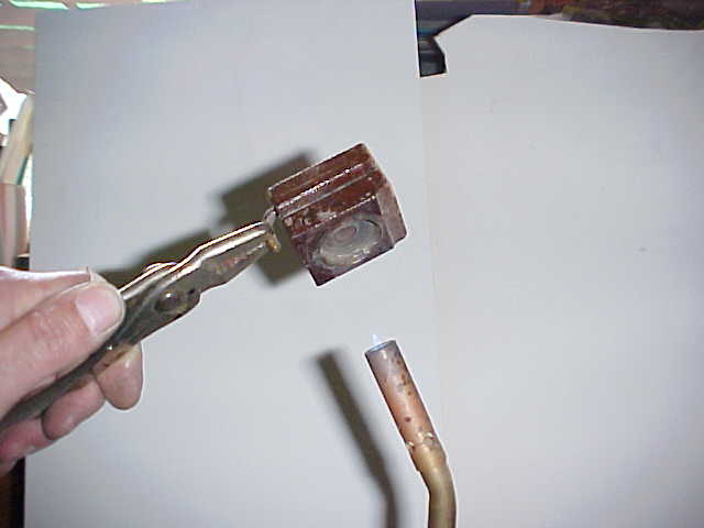
PHOTO B 2 Removing the caps to reveal the valve buttons Holding the elbow with a pair of pliers, the valve cap is passed over the flame of a propane torch for about a second or two. The heat softens the shellac and the valve cap is easily removed with the point from the triangular scraper. With this method the cap is never damaged and therefore can be reused. |
 |
 |
PHOTO B 3 Valve caps removed There is little difference from the interior of one valve button to the next. The buttons are almost the same apart from location of the felt from the top of the pouch disc to the bottom of the valve stem. This felt eliminates noise between the pouch and the valve. The big change is in the lower seat. Ampico started with a wood seat and changed to a seat made from black shellac. This is the same material used in making old 78 RPM records. The wood seat was abandoned because wood is porous. The black seat is sealed in place and surrounded with burnt shellac making an air tight seal. Take notice that the second valve body has been raised a sixteenth of an inch in height to allow for the additional thickness of the black shellac seat. The second improvement was the new style metal cap. In the next photo you'll see how Ampico came up with the design for this cap for the top seat. |
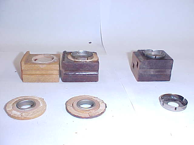 |
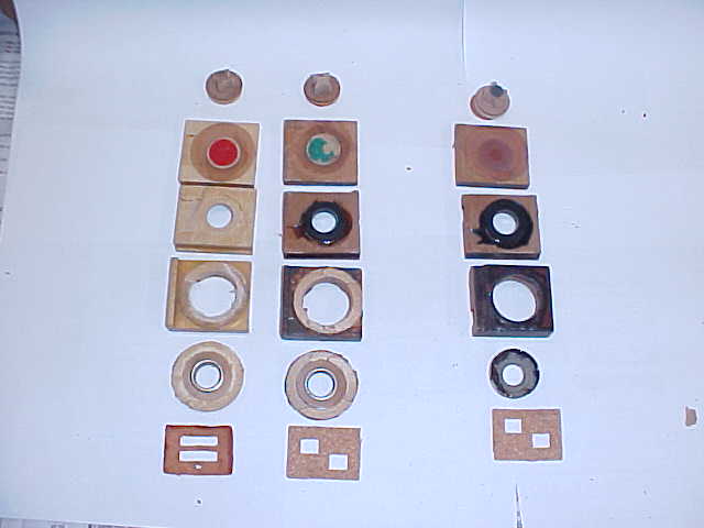
PHOTO B 4 Valve cap transition In this photo I have placed a metal cap on top of the second valve. As you can see, the metal cap was designed to fit into the top of the old style valve without changing the valve body. There were two great disadvantages in the old style wooden valve caps. First, the wooden cap has end grain on its flat surfaces and made a poor joint when glued to the top of the valve body. Secondly, valve travel was not easily set. In the earliest valve, the cap was glued in place with a gauze gasket. Later, Ampico used a cardboard shim in between the cap and the body of the valve. The paper made for a poor seal and over time would come delaminated and lose its airtight seal. The metal cap is secure in the well and shellacking the edges makes for a perfect airtight seal. The metal cap has the advantage of being easily adjustable so the valve travel may be set accurately. The importance of valve travel will be discussed in section B 20. I've left a space between the second and third valves in this photo. There was a transitional valve that was made for a very short time. The transitional valve used the metal caps without raising the height of the wooden valve body. The missing valve eliminated the wooden disc and used a very thin brass disc in its place. This valve was probably in production no more than a month or two. The design was most likely abandoned because the valve leather had to be attached to the brass disc with shellac. Shellac was the only choice of fixative available in the mid-twenties, as other glues had not been developed. Shellac does not permanently bond to brass, so the logical change was to make the valve body higher to accommodate the pressed cap along with the wooden valve button. These later valves have a small punching of green cloth glued to the bottom center of the wooden disc. The purpose of this cloth was to eliminate noise between the valve stem and the wooden disc as the valve stem was pushed up by the pouch. |
|
PHOTO B 5 Totally disassembled valves The valves have been taken apart to show the different parts that make up each valve. It is not necessary to take them apart to this point for restoration. The lowest section must be spit off in order to replace the pouch. I use a dulled single edge blade as a wedge to break this joint. A sharp razor blade will cut into the wood rather than following the glue joint. Place the blade on the joint on each side of the valve and tap it lightly. The valves can be split apart with out destroying the wooden sections. Occasionally a small piece of wood is split from one section and must be glued back in place before proceeding to the next step. |
 |
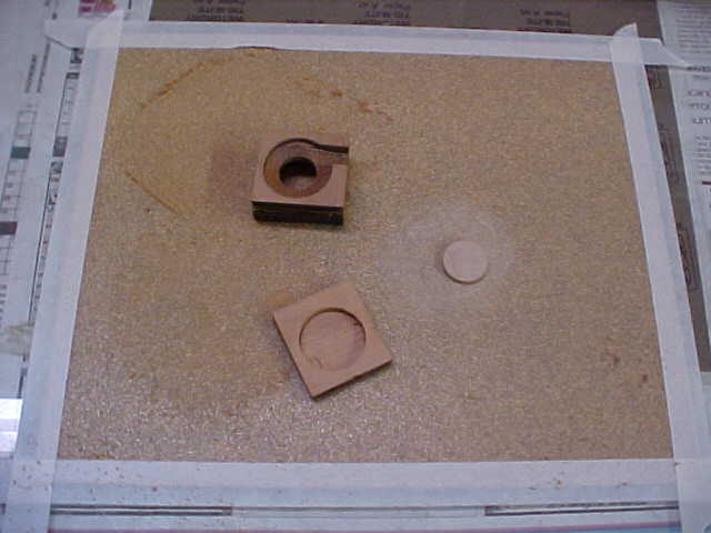 |
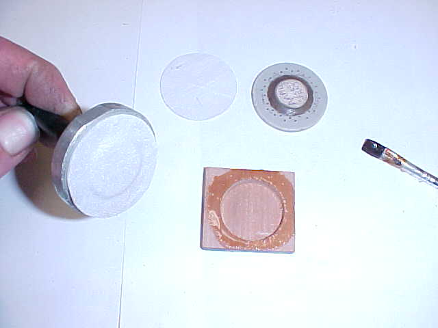
PHOTO B 6 Resurfacing Resurfacing is the most important technique in valve work. This process creates surfaces that are perfectly flat. After resurfacing, the valves will be airtight against their seats. Resurfacing will also create very good glue joint between the pouch board and the main valve body. A quarter inch thick piece of plate glass is a true surface. Tape a piece of sandpaper to the glass using masking tape. The masking tape holds the sandpaper down on all four sides. This stops foreign particles from working their way under the sandpaper. Different grades of paper will be used for various operations. Equal pressure is applied to the object being sanded. The object is rubbed on the paper in an orbital manner. The object is dropped, turned 90 degrees and rubbed in an orbital pattern again. Check to see if the object has been sanded true by drawing pencil lines on the surface that has been sanded and rub it gently on the sandpaper. If the pencil lines are rubbed off evenly, you have resurfaced the object properly. In this photo both sides of the valve disc have been resurfaced in preparation for new valve leather. The pouch has been sanded off as well as the bottom of the valve body that the pouch board is glued to. Although it is not demonstrated in this photo, I coat the inside of the pouch well with flake shellac before resurfacing the pouch board. Shellac is applied to the well and after the shellac has dried, the top of the pouch board is resurfaced. This way any shellac that gets on the wood that is going to be part of the glue joint is removed during the sanding process. There cannot be any shellac on the top of the pouch section, as hot glue will not stick to shellac. The pouch wells are coated with shellac not to make this area airtight, but to cut down on loose wood particles that were created when the pouch well was drilled. If you look closely at the sides of the well you will see that the wood has been crushed during production. Any loose wood fragments or dust in the pouch well could make their way into other components and could cause problems. |
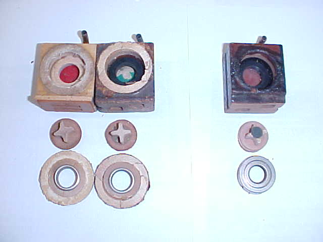 |
PHOTO B 7 Valve seat types This is the second time we're looking at this photo. In section B 6 the valve button was resurfaced. Now the seat the valve button rests on must be resurfaced. In the early valve the wood seat must be resurfaced. In the later type valve the black shellac seat must be resurfaced. |
|
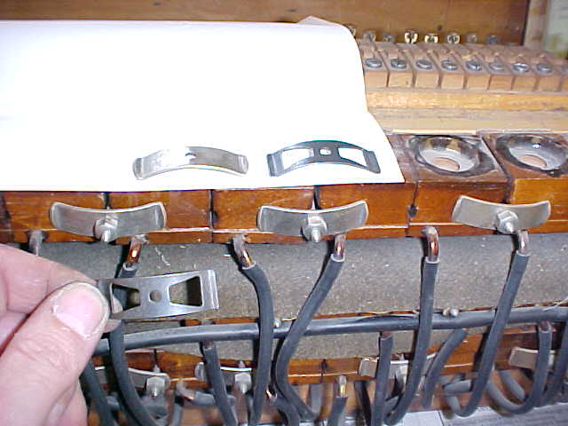
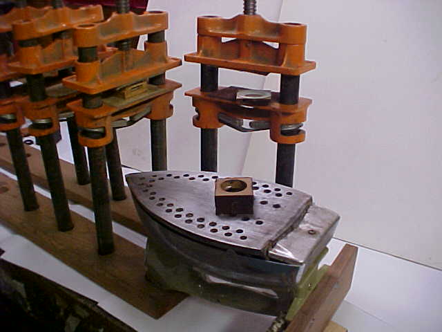
PHOTO B 8 Valve springs on a grand stack This view shows how the unit valves are held onto the stack. In a grand stack, the valves face the tail of the piano. There is a cork gasket in between the unit valve and the front of the stack. These units are not glued onto the stack. They rely on the metal springs to make an airtight seal against the stack. I'll be showing more pictures of this stack throughout this guide. This stack came out of a Chickering grand that I restored in 2002. It was restored by someone whose only interest was to make "fast money." Much destruction has been done to it, as you will see. The valves were treated so poorly that they were not restorable and so I used an untouched set of valves from a parts stack. As you can see in the photo, the original nickel plated springs have been over tightened in an effort to keep the piano playing. These springs are very thick and do not have any give to them. Even under the best of circumstances these springs crush the wooden valve bodies and warp the inner seats. These springs were designed for the 1920 upside down blocks which were made out of maple. Maple blocks hold up very well with these springs, but the early maple blocks were only in production for about two years. These darker colored valves made of red gum wood were made for the next six years and these heavy springs were always used to hold them in place. The spring I'm holding in the photo was developed for the model "B". They are much thinner and have a lot of give to them. The model "B" springs do not tend to warp the valve bodies. These "B" springs were a definate improvment and so the original heavy springs will be thrown away and replaced with reproduction "B" springs. |
 |
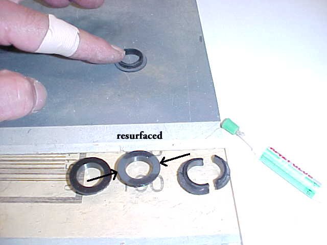 |
PHOTO B 9 Truing the black shellac seat In the forefront of the photo you will see a black shellac seat that has been partially resurfaced. Notice the grey areas the arrows are pointing toward. The grey areas have been sanded have been sanded first by the resurfacing process. This seat has warped because the metal springs that hold the valves in place have crushed the valve over time. This clearly shows why the early springs must be done away with. Also, if the seat has warped to the point where the center hole is oblong rather than round, the seat must be discarded. Even if the warping is slight it is important to resurface the seat. A slight loss of vacuum in each valve multiplied by the number of valves in the player mechanism will add up to a great loss of power. The old black shellac seats will be removed so they can be reinstalled with fresh flake shellac. Fresh shellac will insure a good seal that will last a long time. Tape a piece of (dry) 320 wet/dry paper to the glass to resurface the black shellac seats. Restored unit valves should last fifty years or so without service. I usually break two or three shellac seats in the process of removal. Turn the seat upside down against the glass and glue the pieces back together with instant glue. (After you glue them with instant glue move, them over a little so that you don't glue them to the glass). You may break a lot of these seats the first time you work on an Ampico. If you break a lot of them and can't glue them back together, new replacement aluminum seats can be purchased from Bob Streicher. Leather reacts with aluminum over time causing the aluminum to oxidise so I prefer to re-use the shellac seats. Aluminum seats should be sprayed with brass/metal lacquer to prevent the leather from reacting with the aluminum. If you get discouraged breaking the old seats out you can use a piece of 320 wet/dry paper glued on the end of a dowel to sand the seat without removing it from the valve body. This method will work only if you make sure the end of the dowel is true. |
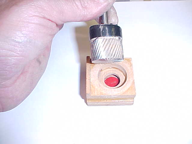 |
PHOTO B 10 Truing early wood seat This rotary file that can be purchased from Manhattan Supply Company. This file is used to resurface the seats in early valves. This tool must never be used in a power machine of any sort for working on valves, that would be dangerous! This tool has VERY sharp edges on it and so the top of the tool has been covered with several layers of electrical tape to protect my hands. The resurfacing process of the inner seat of this early "upside down" valve is done by hand. Do not put the tool in a holder of any kind because you have to feel the flat end of the tool rest evenly against the wood valve seat before turning it by hand. It just takes a few seconds to true up an early valve seat with this method. To check to see if the wooden seat is true, draw light pencil lines on the wood valve seat and gently turn the file in the valve well to see that all the lines are being scraped off in a consistent manner. |
|
PHOTO B 11 Setting the pouch A friend of mine made up this pouch setting tool for me many years ago. I have included a drawing of this tool at the end of this guide. To use the tool, a Teflon disc is inserted onto the aluminum body. The Teflon disc has many small holes drilled into its perimeter and cardboard punchings of the appropriate thickness have been glued to its center to create the proper dip in the pouch. The Teflon disc is easy to clean. A damp cloth wipes glue from the disc in between setting each pouch. This pouch setter is connected to a suction box with variable speed control. The vacuum level of the pump is turned down as low as possible to about eight inches of vacuum. With the help of this tool you will be able to install a set of pouches quickly and consistently. The pouches are glued in with hot glue. |
 |
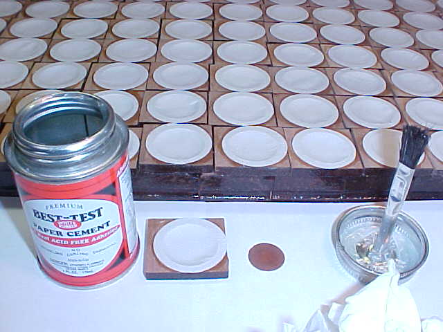 |
PHOTO B 12 Rubberizing the pouch After the pouches have been glued in, they are rubberized with thinned down rubber cement. Remember: the goal of rubberizing the pouches is to leave the rubber in the holes of the pores, not on the surface of the leather. Rubbing as much of the rubber off as you can will force some of the rubber into the pores. Talcum powder is brushed onto the surface so the rubber is no longer tacky. It is a very good idea to dust the nap of leather of newly covered valve buttons (primary and secondary) with talcum powder to make sure they work freely as well. Leather, (animal skin) has pores throughout its surface just like human skin. Pores in pouch leather are very small holes that allow a minute amount of air to pass through its surface. Pouches must be rubberized to produce a consistant airtight quality in the leather so they will operate poperly with consistent bleeds. A porous pouch is in essence creating a larger bleed. A pouch with too large a bleed (a porous pouch) will be slow to respond to an "on" signal and too fast to return to "off". |
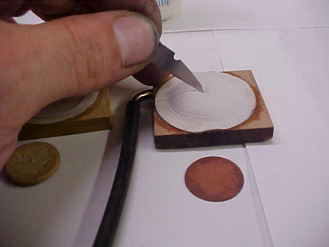 |
PHOTO B 13 Attaching the valve disc This is my own method of attaching the disc. When I'm disassembling Ampicos in original condition, I usually find a couple of these lifter discs detached from the pouches. I adopted a method that will prevent the disc becoming unglued from the pouch. Because the pouches are rubberized, glue will not adhere to the leather. Attach a rubber tube to the pouch and blow into it. While the pouch is inflated, use a broken razor blade to score a very small area of the pouch leather (about a three sixteenth inch circle) in the center of the pouch. Scratches are made on the surface of the leather by raking the blade crosswise, not up and down. In this way the leather is scored, not cut through. A drop of glue is placed on the scored area. The glue seals all of the scratches and makes a mechanical bond between the pouch disc and the pouch. To prepare the disc for gluing, scrape the old glue from the bottom of the disc and roughen up the center of the disc a bit where the glue is to be applied. |
|
PHOTO B 14 Gluing the pouch board back to the block "C" clamps should not be used for this operation as the clamps will twist when they are tightened. I use six Pony clamps to glue the valve blocks back together. The top and bottom surfaces of the Pony clamps have been lined with thick leather to prevent the wood block from being marred. Pony clamps exert positive downward pressure on the unit valve and exert enough pressure to form a proper glue joint. It takes quite a bit of pressure to glue the pouch board to the main body of the unit valve. Set the top of the valve on the iron to warm up the wood. Warming the wood will give added working time before the glue sets. Heating the top portion of the valve body will also help warm the hot glue under the pouch, which helps to make a good joint. Apply glue to the joint and place the block in the clamp. Tighten the clamp until some glue squeezes out of the joint. Before tightening the clamp all the way make sure the top and bottom of the valve are lined up so that the wood sides will not have to be sanded to even them up. Let the glue set for an hour and a half before taking the valves out of the Pony clamps. The dimensions of each unit valve will vary slightly so when the valves are split apart keep the tops with their original bottoms. If the upper portion of the unit valve has been compressed by the spring clamps and has less depth than the pouch board, line up the nipple side of the valve when clamping rather than the side of the valve block that the gasket is glued to. |
 |
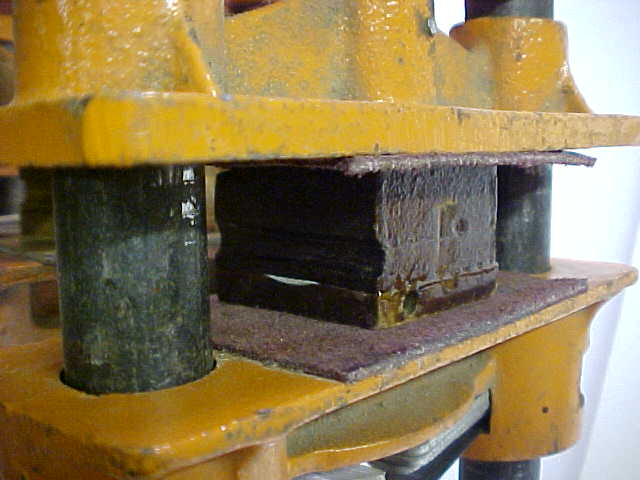 |
PHOTO B 15 Close up of valve in clamp In this close up of the valve in the clamp you can see some glue squeeze out the joint. Too much glue squeezing out would mean you applied too much. Make sure you have a wood to wood joint. When you are done sanding the sides of the valve there should be a very fine line at this joint. If there is a visible layer of glue at this joint, the joint is too weak and may come apart during the life of the restoration. |
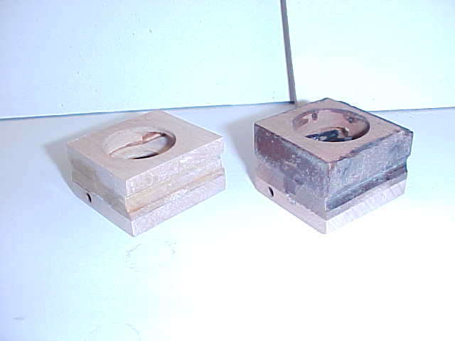 |
PHOTO B 16 Early and late valve after sanding sides The valves have been sanded to even up the sides. The sides of these valves have been resurfaced on plate glass using sandpaper of 80 or 100 grit. It is not necessary to remove all the old shellac from the sides. It is important to keep the wood square, especially on the side the gasket is attached to. Don't ever use a belt sander on the wood blocks. Do ALL your sanding of the unit valves on the plate glass. Notice the new wood joints look as fine as the originals. The valve blocks will now be coated with flake shellac. The alcohol in the new shellac will cause the old shellac to flow so that it may once again be an effective sealant. Two coats will be applied to the early valve to bring up its color. The late valve will be touched up where it has been sanded and only one coat is needed on the entire valve after that. |
|
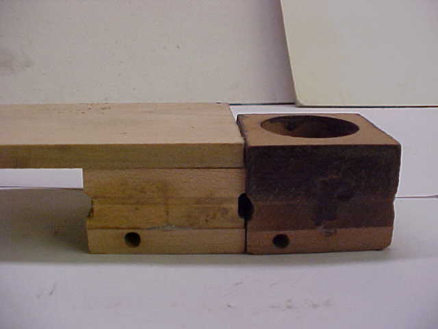
PHOTO B 17 Adding wood cap to an early valve This is my solution to restoring the early style valves with wood caps. I resurface the top of the old style valve and add a piece of poplar to make it the same height as a late style valve. I score the wood and glue it together with Titebond glue. Then I clamp it in the Pony clamp. |
 |
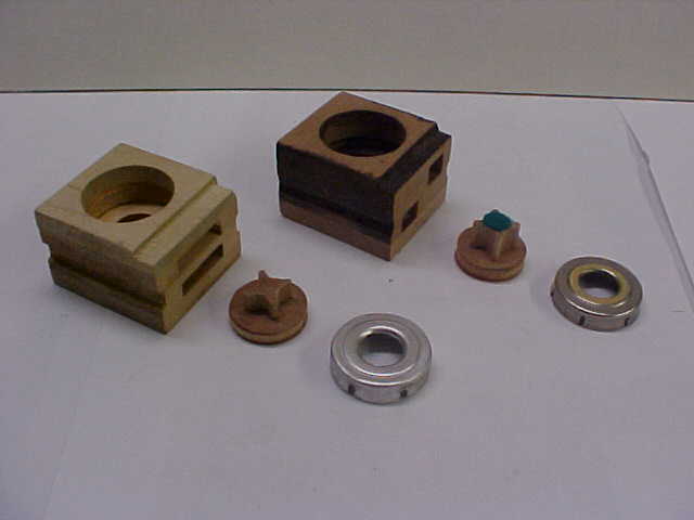 |
PHOTO B 18 Valve buttons and caps The upside down valve is shown on the left. A jig is set on the drill press to bore the hole in the new top. The holes are not bored exactly the same in every unit so some wood will be removed from the inside of the valve. A FORSTNER bit is set in the drill press to stop about an eighth of an inch from the wooden seat inside the valve. A cut has been taken on the top of the early valve with a table saw to match the notch in the top of the later style valve. Reproduction metal caps have been purchased for the upside down valves. With the new metal caps the valve travel on the early valves can be set the same way as the later style valves. |
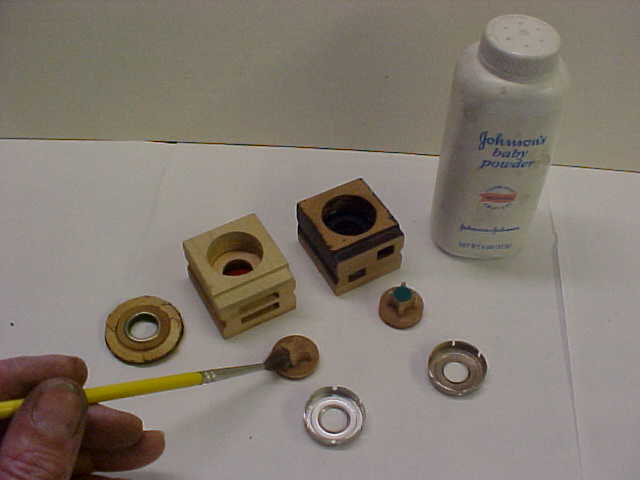 |
PHOTO B 19 Applying talc to the buttons The buttons have had new kidskin applied to them with the nap side facing out. Talcum powder is brushed on the valve leather to make sure the button works freely. Valves of all types should halve talc applied to the leather before installation. The late style valve on the right had its metal valve cap cleaned in the ammonia solution. The old metal cap has been resurfaced on the glass with dulled 320 paper. Then both the old and the new caps were sprayed with brass lacquer to prevent the leather from reacting with the metal. |
|
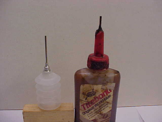
PHOTO B 20 Shellac applicator On the right is a commercially available squeeze bottle. This type of applicator can be used if you are going to restore an occasional piano, but this style is inconvenient. These bottles are very hard to fill due to the narrow neck and the metal top sometimes leaks where it joins to the bottle. An applicator can be made out of an old glue bottle. The glue bottle is easy to fill and it holds a good quantity of shellac. When not in use, the top can be sealed with a piece of masking tape. Occasionally, the metal tube will have to be cleaned with a piece of piano wire. |
 |
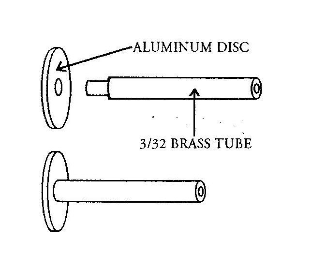 |
Build Shellac applicator To make a shellac applicator, start with a brass tube three thirty seconds of an inch in diameter. You can buy brass tubing at a hobby store. Make a disc out of aluminum or brass about one sixteenth of an inch thick. The diameter of the disc should be the same size as the neck of the container. Reduce the diameter of the tubing on one end by hand or by filing it down in a drill press. Then drill a hole in the disc to make a snug fit with this reduced end. The reduced end should protrude through the disc about a thirty- second of an inch. Peen over the protruding tube end to fix the tube to the disc. Or you can solder the brass tube onto the brass disc instead. |
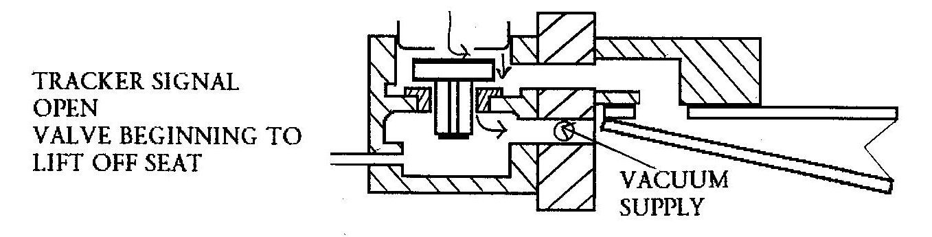 |
VALVE TRAVEL When the hole in the tracker bar is uncovered it only takes a split second for the valve button to travel to the top seat The first illustration shows a valve as it is being lifted off its lower seat. In the time it takes the valve to travel to the top seat, vacuum is lost through the top seat. A valve with less travel will lose less vacuum. It is important to reduce the valve travel to cut down on this loss of vacuum. |
|
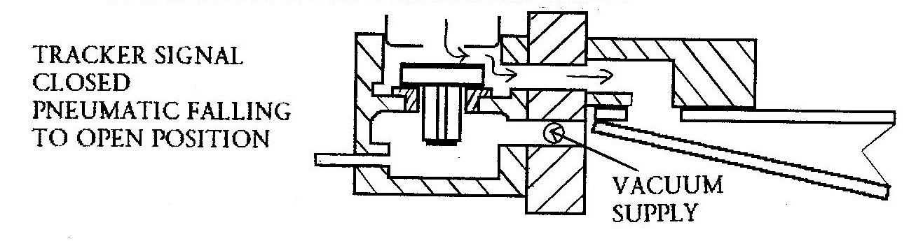
The second illustration shows a valve just after the hole in the tracker bar has been closed and the valve has come to rest on it's lower seat. The pneumatic opens by admitting atmosphere through the top seat. If the valve travel is too low, the pneumatic will be slow to open as the atmosphere admitted through the top seat will be restricted, therefore repetition will be limited. A balance must be found so the valve travels as little as possible when activated, without restricting the pneumatic from falling to the open position when the valve comes to rest on its lower seat. Ampico secondary unit valves were set from the factory with a travel of forty to forty five thousandths of an inch. These unit valves can be set to travel at thirty six thousandths plus or minus one thousandth. This travel will make them efficient. |
 |
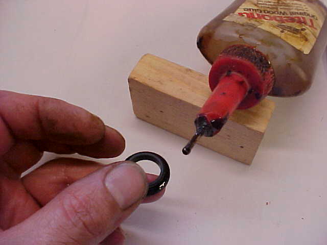 |
PHOTO B 21 Shellacking the seat Clean most of the old burnt shellac from the black shellac seat. The triangular scraper can be used for this job. Too much scraping can cause the seat to break. The inside of the wood valve body has been scraped of most of the old burnt shellac with a sharpened screwdriver. Run a bead of shellac on the underside of the black shellac seats before installing them. It is fine to run new shellac over the old. The alcohol in the new mixture will melt the old to make it viable. Some shellac must be scraped from the inside of the hole that the seat goes into or you may crack the seat when you reinstall it. |
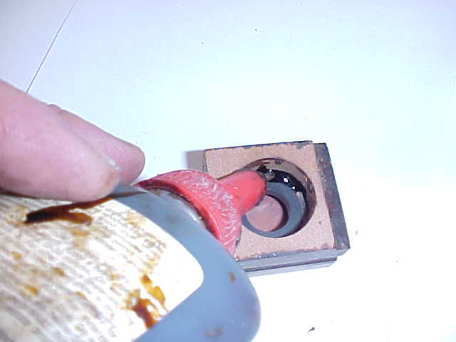 |
PHOTO B 22 Running Shellac around the outside of the seat Next, run shellac around the seat just as it was originally. The shellac seals the wood to isolate the upper chamber connected to the pneumatic from the pouch chamber below. |
|
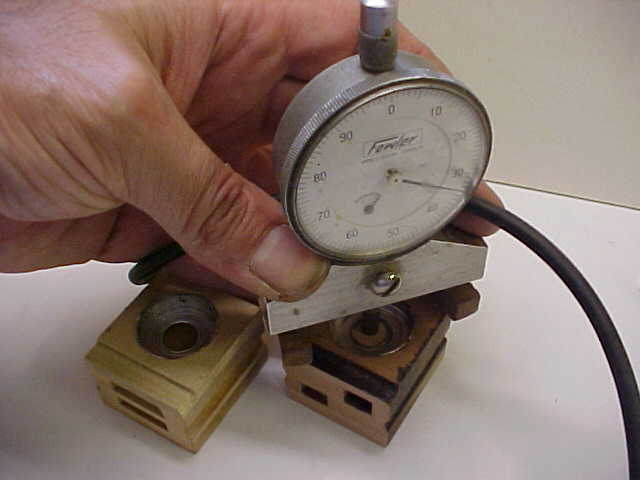
PHOTO B 23 Traveling the valve I have added feet to allow this dial indicator to stand flat and I've also put an extension on the micrometer stem so that it will extend down far enough to rest on the top of the valve button. In forcing the metal caps into the well valve travel can be set accurately. If you have taken the time to resurface the wooden top of the unit valve as shown previously, you will find it helpful in determining whether you have the valve cap in parallel to the top of the valve button. The factory set these valves between 40 and 45 thousandths of an inch travel. While blowing into a tube attached to the pouch section, set the travel to 35 thousandths of an inch (plus or minus one thousandth). Valve travel below 34 thousandths may not be enough to allow your pneumatic to fall back to the off position quickly. |
 |
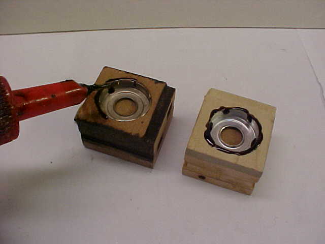 |
PHOTO B 24 Sealing the cap The next step is to seal the caps, paying close attention to sealing the vertical breaks in the inside edge of the cap as shown here. I didn't have time to prepare a mixture of shellac for this photo so it's a little too thin for this application. The shellac will run down a little inside the cap but it should be thick enough that it doesn't run freely. |
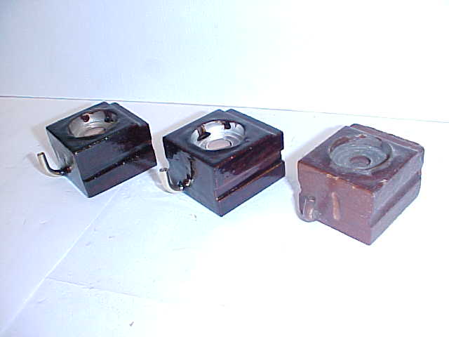 |
PHOTO B 25 Completed Valves The valve on the right is in original condition. The valve on the left is the late style valve and the one in the middle is the upside down valve. Even though I've changed the design of the early upside down valve, it looks proper and it is very accurate. I believe the improved valve will outlast the original design by many years. |
|
on November 8, 2022 by John A. Tuttle, who Assumes No Liability For The Accuracy or Validity of the Statements and/or Opinions Expressed within the Pages of the Player-Care Domain. Player-Care offers some of the parts shown in this page -click here. This page was last revised on December 18, 2024. |
|
407 19th Ave, Brick, NJ, 08724 Phone Number 732-840-8787 (Voicemail Only, No Texts) |
