
|
|
|
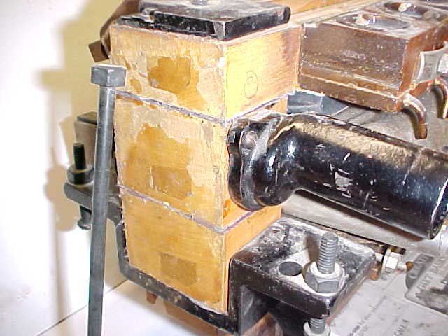 |
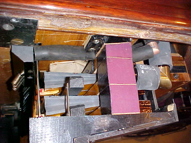
Photo C1 The Stack Side View This is a photo of the end of a grand stack. It is similar in design to the stack used in uprights as well. In this section I will be addressing two weak points in the design of an A stack. First, the end plugs, shown here as trapezoid shapes, will shrink over time causing the stack to lose vacuum through the old glue joints. Secondly, the bolt holding the three tiers together will loosen over time creating a leak between the tiers where they join at each end. The ends of the stack are of end grain which is very porous. The factory used a thick coating of shellac to seal the end grain. As you can see, some of the shellac has flaked off over time. The three tiers are connected pneumatically by a large air channel running vertically through the three tiers at each end. Each end of the stack is held together with a single bolt. If you look carefully, you can see the threads of the bolt sticking up through the top casting. I placed a spare bolt in the photo leaning against the end of the stack. The factory sealed the tiers together with cork gaskets coated with burnt shellac. When the wood comprising each tier shrinks due to a drop in humidity, the shellac seal fails and the cork gasket breaks away from the wood. When this happens the tiers will leak around the cork gaskets are and the stack will lose a great deal of vacuum. The replacement gaskets will be cork of the same one sixteenth inch thickness. If the thickness of these gaskets is changed, the relationships of the tiers to one another will be changed and the pneumatics would not rest with same size opening from one tier to the next. These gaskets should not be replaced with leather because it would be very difficult for the next restorer to separate the tiers again. Use Sobo to glue these gaskets in place. Glue the cork gasket to each tier while the stack is apart. After assembling the stack, brush glue on a thin putty knife. Work the glue in the three joints onto the cork gaskets with the putty knife and then tighten the long bolt until it is snug enough to secure the joint. Before tightening the bolt all the way, push on the three tiers so they line up vertically as well as horizontally. Glue one side of the stack and then the other. After the glue has had a chance to set a bit but before it has dried, tighten the long bolts all the way. Using this method the tiers will remain sealed through the live of the restoration. The cork will make it possible for the next restorer to separate the tiers. |
|
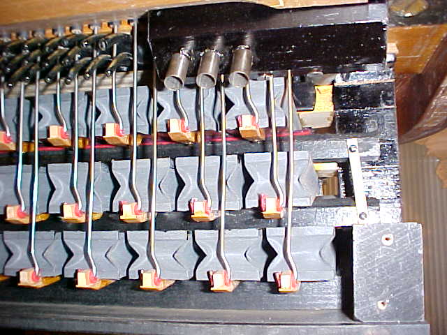
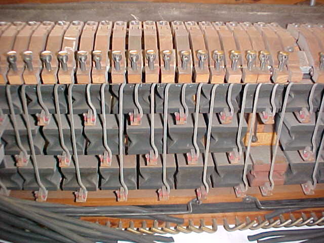
PHOTO C 2 Tier gaskets (early stack) To get the most expression from an Ampico "A," make sure the pneumatics are opened the same amount from one tier to the next. If the cork gaskets on the end of the stack are replaced with one sixteenth inch thick cork, the pneumatics on late style stacks will have consistent open ends from one tier to the next. The wooden arms on the top of the stack rest on a common rail, and the factory has the proper length poppet wires for each tier so the openings on the pneumatics on every tier will be the same. The open ends of the pneumatics will be consistent most of the time for the early style stacks as well. The early stack in this photo is an exception. Early stacks are designed to have the bottom leaf of each pneumatic rest on a felt covered rail. If you look closely at this photo you will see that I had to shim the upper tier rest rail with two additional layers of red nameboard felt to raise this section of pneumatics up. A factory workers did not take the proper care when they installed this rest rail. The more a pneumatic is opened, the more force it has. This principle is applied when adjusting the zero setting on your expression mechanisms. The leather nuts on the threaded rod are turned to affect the span of the spring pneumatics. The spring pneumatic is opened more if you want the zero setting louder; or closed more if you want it softer. On the Ampico "B" stack, individual key pneumatic spans can be adjusted so that all the notes play consistently on the softest passages. This adjustment makes up for inaccuracies in the piano action. Ampico "A"s perform very well at low vacuum levels as long as the piano action is well regulated. In the Ampico "A" Inspector's Reference Book there is no vacuum measurement given for the zero intensity setting. The zero vacuum level is different for each piano and differs depending on the weight of individual piano actions. If the action is heavy, the zero setting will be greater than with a lighter action. If the mechanism is set to play softly and a couple of notes won't play, it is due to poor regulation of the piano action. With a well-regulated piano action, the zero setting may be adjusted to such a low vacuum level that the piano will play too softly (it will no longer be musical) without having any notes drop out. This is a sign that your action is in A-1 shape. With your piano action in fine regulation the zero intensity can then be set on a musical basis. |
 |
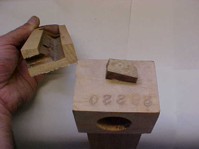 |
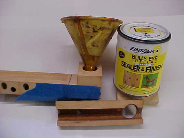
PHOTO C 3 End plug Scrape the old shellac from the end of the tier and knock the plug out. It is not necessary to knock out the plug and re-glue it, but I always do unless it is particularly stubborn. After the old shellac is scraped off, glue pneumatic cloth on the end of the tier. I am holding part of a tier that has been sawed open. There is a common channel routed through the length of each tier. This common channel was routed through the end of the tier and therefore an end plug was needed. In the center of the stack there is a divider of the same configuration as the plug separating the bass expression from the treble. This divider is less than a half an inch thick. This divider also tends to shrink and will cause leaking from the bass end to the treble end. This leak will take away from the expression and so it must be resealed. The entire inner chamber must be resealed with fresh shellac to get instant and subtle response from the expression. Notice how much shellac the factory used to seal the maple. The factory considered it essential that this inner chamber be absolutely airtight. |
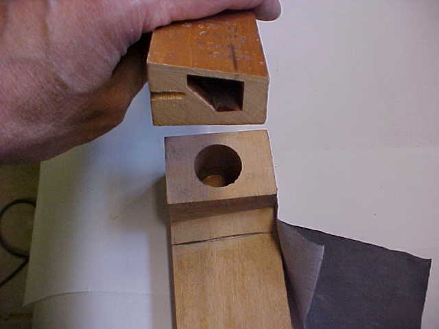 |
PHOTO C 4 Sealing joint On the opposing side from the plug there is another weak point. I am holding a cross section of a tier in my hand. The top of this chamber is covered by a single piece of maple, one eighth of an inch thick with its grain running the length of the tier. There is no support for this thin maple over the center of the channel. This thin wood often sags a bit and so it is a good idea to secure the glue joint where the cap covers the thin wood at the end. Glue a piece of pneumatic cloth from the pencil line I have drawn, all the way up to where the gasket will be glued on to the cap. Take the step of gluing this pice of pneumatic cloth on his area as well as gluing pneumatic cloth to the plugged side of the end before the interior of each tier is sealed with fresh shellac. |
|
PHOTO C 5 End completed Here is a photo of an early restored stack after restoration installed in a 1923 piano. The piano's treble leg as been removed for this view. The pneumatics face toward the keyboard. The front of the keys are about a foot and a half away from the pneumatics. The fingers that hold the poppet wires to each key pneumatic are held in place by a single screw. This is a weak point with the design. If you are the first person to restore a stack, you should not strip any screws when re-attaching these fingers. Before re-attaching the fingers, drill the screw hole in each finger out so the screw can easily pass through it. If they are not drilled out it will be difficult to get a secure joint when the fingers are glued back in. When removing the fingers sometimes a chip of the pneumatic stays on the finger. If this happens, remove the chip with a razor blade and glue it back on the pneumatic. In clearing the fingers of wood chips and removing the old glue, the fingers do not have to be numbered during the re-bushing process. Sand the old glue from the fingers with a hammer file and scrape the old shellac from the sides of the finger. It takes a lot of time to clean the,, but you don't want to get the stack into the piano to find that a finger has come loose. This prep work will produce a very good wood joint. When the fingers are glued back in place with hot glue, run some glue up along each side of the finger to add more strength to the joint. If a screw strips when installing a finger, drill a hole in the finger a little closer to the poppet wire and move the screw forward. While sanding the old cloth from the pneumatics,sand the old shellac from both the top and bottom surfaces of the pneumatic boards. After the pneumatics are glued in place and the fingers are attached, brush at least two coats of orange shellac on the top and bottom surfaces of the pneumatic boards. This will make the pneumatics airtight. |
 |
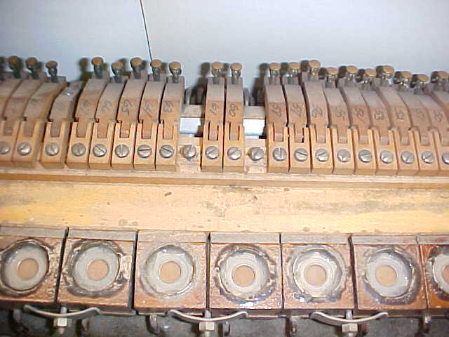 |
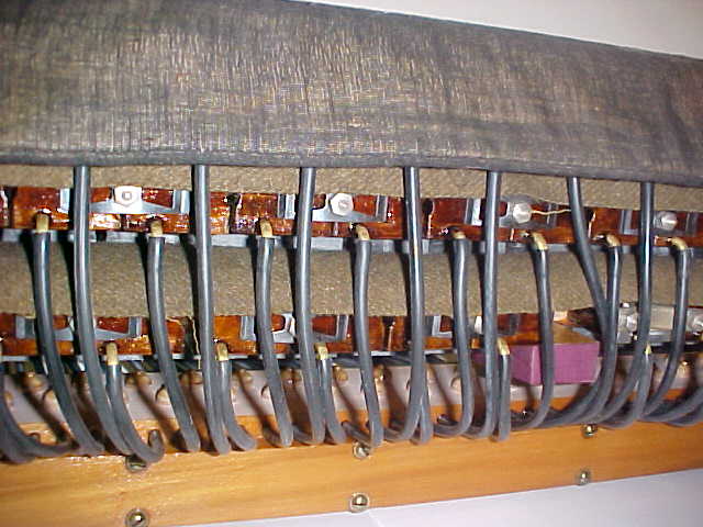
PHOTO C 6 Late style arms This stack has been worked on once before and much of it has been destroyed. In this photo you can see that two of the arms have been removed. They were probably lost or broken by the fellow who rebuilt the stack. This is the way I found the stack when I removed it from the Chickering. Of course these two notes never worked. An aluminum channel topped with action cloth runs under these fingers to support them. This aluminum channel is the soft pedal compensation rail. When the soft pedal is on, the back of the keys are raised up off the stack. Three pneumatics on the lower tier of the stack are tubed to the soft pneumatic. These compensating pneumatics raise the aluminum rail up to take the fingers to the bottom of the keys. On early stacks, the key pneumatics were five inches long. On late style stacks the key pneumatics are four inches long. The longer pneumatics on early stacks behave differently then those on the later stacks. When Ampico shortened the length of the key pneumatics they found it necessary to add the soft pedal compensator. Early stacks perform just as well without a compensator. The later stacks are easier to work on and more compact. From a musical standpoint I prefer the early stacks. The long pneumatics give greater power for a more dynamic performance on loud passages yet are very gentle for soft effects. |
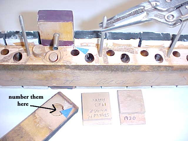 |
PHOTO C 7 Marking the pneumatics This stack has had extremely poor work done to it. It can hardly be called a restoration. Before removing the pneumatics, make a jig which measures the overhang of the hinge end of the pneumatic. Every stack will be a little different. In the foreground of the photo there are two examples of these jigs from previous stacks I have restored. In the lower left hand side of the photo there is a pneumatic with a blue arrow on it pointing to a darkened line. If you are not the first person to rebuild an Ampico stack you can look for this original factory mark. This mark was left as a result of the glue in the valve area being scraped clean from the pneumatic. This line can be used to make a jig. The jig will be used when it is time to glue the pneumatics back onto the decks to achieve the proper overhang of the tail. Carefully mark the location of each pneumatic with a sharp pencil. Be as exact as you can. This will help to keep all the poppet wires parallel to one another upon re-assembly. If there are any spaces that do not contain pneumatics draw a circle as I have. When removing the pneumatics it's a good habit to number them on the inside as indicated. It is a sign of craftsmanship to have a restored mechanism look as original as possible so number the pneumatics where it will not show. Mark the number of the pneumatics on the tier in the valve area. If any wood remains on the deck remove it and glue it back to the pneumatic. I do not use a gasket when I re-glue the pneumatics back to the decks. Mark on a piece of wood the exact length of the threaded spring rods to use as an indicator for reinstalling. These threaded metal rods hold the valves springs in place. Gripping the metal rods below the treaded area, use a vise grip to unscrew them. They can be reinstalled with the vice grips or you can make a device to reinstall them by taking a length of old lever rod and filing one end to fit into the universal handle used for regulating tools. Drill a hole in the other end of the rod and tap it to match the threads on the threaded spring rods. |
|
PHOTO C 8a Crooked poppet arms. Chickering stack before restoration Here is what happens if you are not careful in marking the exact location of each pneumatic. The arms will be unevenly spaced. Many rebuilders get into this situation and then start bending the poppet wires. There is no reason to turn out work like this. If the poppet wires are not in their proper place this becomes a particular problem when working on early stacks. It will be very difficult to get the upper tier poppets to travel vertically as misalignment will cause the arms to travel diagonally. If I am working on a stack that was not marked properly, I will always make new moveable leaves for the stack pneumatics out of poplar and line up the poppets properly. This is easy to do on late stacks. On early stacks remove the guide rail from the back of the keybed and use it as a guide for spacing. |
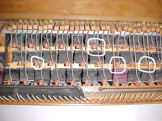 |
PHOTO C 8b Chickering stack after restoration
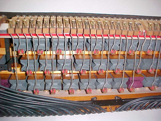
PHOTO C 8C Chickering stack after restoration
|
PHOTO C 9 Properly marked stack These pneumatics were recovered many years ago by a conscientious restorer. The poppet wires are in good alignment. Unfortunately this stack will be used for parts. So much destruction has taken place on the Chickering stack pictured in the other photos in this section that I must take parts from this very clean unit. |
 |
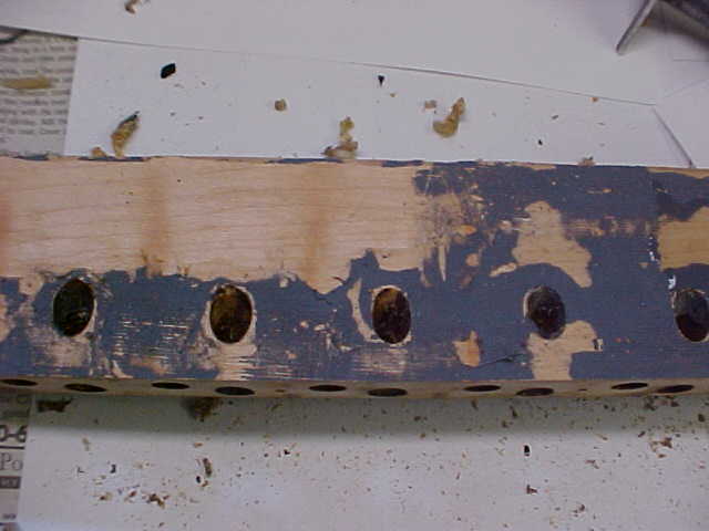 |
PHOTO C 10 Preparing the deck I usually use my triangular scraper to remove the old glue from the deck. And then I use a block to sand the deck flat. It is a very simple job if you are working with an untouched stack. The person who worked on this stack took a novel approach to re-gluing the pneumatics onto the decks. He used plastic glue and then a layer of synthetic Bilon, and then more plastic glue. I had to use an iron the melt the plastic glue and then I scraped and sanded the deck. Due to this person's lack of care, a ten minute job turned into forty five minutes per tier. Extra hours of labor add up quickly when cleaning up after a poor restoration. It may cost twenty or thirty percent more to restore a mechanism with substandard workmanship. |
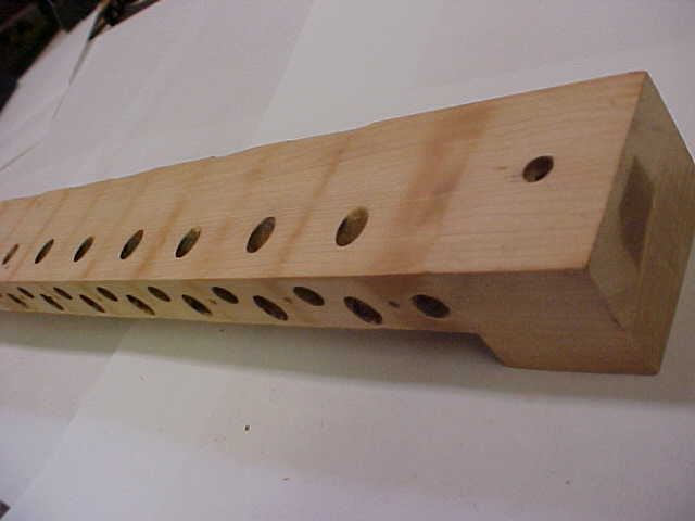 |
PHOTO C 11 Prepped deck Here is the prepared deck. The last fellow removed bits of wood from the back edge of the deck. This will not need to be repaired but there was no reason for this. The stack was treated in a very rough manner. |
|
PHOTO C 12 Sealing the tier Before the tier is to be sealed, protect the deck surface with masking tape. This is a messy job and some shellac is sure to get on the top surface where the pneumatics are to be glued on. Hot glue will not stick to a shellacked surface. If shellac does get on this surface it must be sanded lightly and scored before gluing. The valve side of the deck must also be sealed with masking tape. Do your best to press the tape onto the holes. The alcohol in the shellac will quickly eat away the adhesive on the tape and some shellac will leak out. Pressing the tape on will slow this process down. It's a very messy job so wear plastic gloves and expect that some shellac will end up on the floor. Make sure all the holes on each side of the tier are sealed. Remember the stack is divided in half, so the shellac will have to be poured in both sides. Pour the shellac into the tier. It is not necessary to fill it up all the way. Pick up the tier and turn it in all directions to flow the shellac into all the crevices and then quickly pour it back out. The inside of the tier is shown in the lower right hand side of the photo. There is a lot of old shellac in the channel. The alcohol in the new shellac will soften the old shellac, which will help to seal the chamber. Drain all the shellac from the tier. It is not good to have liquid on old glue joints for any length of time. Remove all the tape on the valve side of the tier so the shellac can dry. After the shellac has dried, you must test the tier for tightness. Tape must be put back on the holes for this test. Usually the tier will only have to be sealed once but I have had stacks that had to treated three times. The inside of the tier should be as air tight as glass. Do not use any other materials to seal the tiers. Other materials may flake off in time. Shellac will be serviceable for the next restoration. |
 |
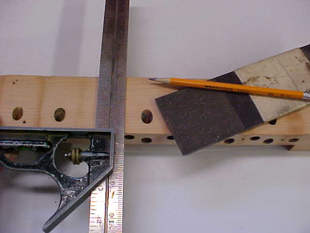 |
PHOTO C 13 Marking the decks Before the marks that locate the pneumatics are transferred from the valve side of the stack to the deck side, use the scoring tool on the gluing surface. A drawing of this tool can be found at the end of the guide. This deck is made from maple which is a very hard wood with no open pores. Without scoring, the wood will not readily absorb hot glue. When the restoration has been completed there will be no marks of any kind on the exterior stack components. After the marks have been transferred to the top of the deck, block sand the valve side of the tier. |
|
The photos in this section are not in the order in which I restore a stack. Here are the steps to go through when restoring a stack: 1. Mark the exact location of each pneumatic on the valve side of the tier with a sharp pencil. Draw circles in pencil where there are any blank spaces. 2. Make a gauge to keep track of the length of the threaded spring rods then remove the rods. 3. Remove the pneumatics and sand the top of the tier. 4. Use the scoring tool on the pneumatic side of the tier, then transfer the lines from the valve side of the tier to the top side. 5. Block sand the valve side of the tier. 6. Seal the ends of the tier as explained in sections C 3 and C 4. 7. Cover the pneumatic side and the valve side of the tier with masking tape. 8. Run shellac through the tier. 9. Sand and use the scoring tool on the pneumatic side of the tier any place that shellac has dripped on to. 10. Glue the pneumatics to the deck. 11. Coat the stationary surface of the pneumatics with at least two coats of orange shellac. 12. Glue the fingers to one tier and then coat the movable leaves with orange shellac. 13. Attach the next tier. 14. After the stack has been completely assembled glue the tiers and bolt them together. |
|
on November 9, 2022 by John A. Tuttle, who Assumes No Liability For The Accuracy or Validity of the Statements and/or Opinions Expressed within the Pages of the Player-Care Domain. This page was last revised on December 18, 2024. |
|
407 19th Ave, Brick, NJ, 08724 Phone Number 732-840-8787 (Voicemail Only, No Texts) |
