
|
|
|
|
PHOTO A1 View of the pump 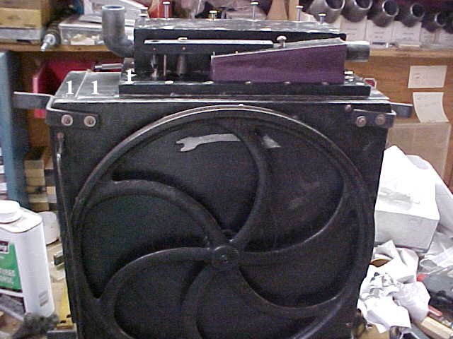 This is a view of the front of an Ampico A pump with the amplifier cover removed. Located at the top of the pump in front is the amplifier pneumatic. The amplifier pneumatic controls the spill valve just to the left of the pneumatic. The amplifier is operational when the switch located in the spool box is set to brilliant. The minimum pump pressure is 20" of water vacuum. When the piano is set to brilliant the amplifier pneumatic creates more tension on the spill valve to reach a maximum value of 30" of vacuum. The expression mechanisms regulate these maximum values down to a minimum of about five inches of vacuum. Next time you're drinking a soda through a straw, take note as to how little effort you need to exert to sip your drink. If the length of the straw is about six inches from the top of the soda, that is just how little vacuum the Ampico is operating on when it is playing at its softest level. The distributor block is located just behind the amplifier pneumatic. This block distributes the vacuum to all the components of the mechanism. The distributor contains a cut off pouch and two chambers which supply conditional or unconditional vacuum. Unconditional vacuum, that is vacuum that is never cut off and supplies vacuum for components like the wind motor, shut off and replay pneumatics. The cut-off pouch is triggered on rewind. The purpose of this pouch is to cut off vacuum to the stack and other components that do not operate while the roll is rewinding. After removing the distributor block, remove the board to which it is fastened. From now on this board will be referred to as the distributor base. Mark the top of the back cover with an arrow corresponding to the arrow on the front of the pump. This marked arrow will always be on the top of the pump. The mark will be covered upon re-assembly by the distributor base so that it will not be visible after restoration. You must mark the back cover in order to return it to its correct position. Use a numbered punch set and number the bellows. The pump is struck in three places on each side as indicated by the number 1 that I have imposed on this photo. The four sides are numbered in the same manner 1-4. Always put each pump cover back in its original location, because the screw holes are not drilled in the same position on each cover. This marking system will enable you to assemble the pump exactly as you took it apart. Problems to be addressed: arm noise, hinge noise, distributor screws stripping, bearing noise. The photos in this section are not in the order that I restore a pump. Here are the steps to go through in restoring a pump in sequential order: 1. Stamp numbers to mark the feeders and feeder covers 2. Mark the back cover with an arrow to indicate the top surface 3. Stamp numbers on each pump arm 4. Restore all pump components 5. Assemble the four feeders and attach the front casting 6. Align the pump arms 7. Assemble the pump |
|
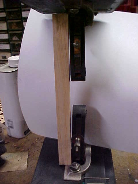
PHOTO A2 Noise in the pump arms This is a side view of the pump. The front and back of the pump have been removed. Also one of the four pump bellows has been removed to demonstrate the first problem that will be addressed. Normally this problem would be the last step in the rebuilding of the pump. This step is being presenting out of order to demonstrate that arm misalignment is inherent in many pumps as they left the factory. This misalignment occurs in almost all Ampico pumps. Earliest examples of pumps use metal arms with ball bearings very similar to Duo-Art spiders. To insure quiet running, these early spiders should be sent to a qualified machinist to have new arms with new bearings installed. You are looking at two opposing pump arms. A stick has been placed along the left side of the arms to show that these arms are out of alignment. Misalignment causes the cloth bushings in each arm to be stressed because the pin is riding on just a portion of the bearing surface. Most of the time the misalignment will not be severe enough to cause a problem, but if it is severe enough this situation can cause the pump arms to knock. The factory used very soft wood for the top side of the pump bellows. When the bolts holding the feet to the pump were tightened at the factory, this soft wood became crushed and the arms were thrown out of alignment. In some pumps you will find that the three eighths inch diameter pin in the metal foot is not set in straight. This will cause a compound problem. In this case some restorers choose to send the foot to a machinist to reset this pin. It would be easiest to request to get a spare foot from another collector. After the pins are set straight you are still left with misaligned arms due to the wood being crushed under the foot. |
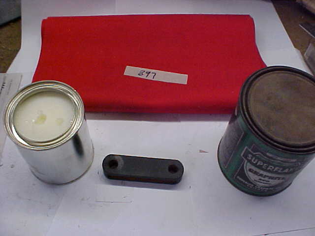 |
PHOTO A3 Re-bushing The Arms Use your numbered punch set and number each arm to coordinate with the pneumatic that it is attached to. Before you attend to the arm misalignment you must first re-bush the arms. This is a standard operation. A strip of bushing cloth is ripped to the correct width using the original cloth as a sample. Hot glue is applied to the cloth and pulled through. The arm is then placed on the foot rod and the spider rod until the glue has set. The new bushing should be very snug on the rod. If it is not, you must use thicker bushing cloth. Schaff Piano Supply offers two grades of bushing cloth. I always use the high grade cloth. High grade bushing cloth can be distinguished from average grade bushing cloth because the high grade has a white center whereas the inexpensive cloth is solid red. After the arms have been re-bushed it is time to go through the important step of lubricating the bushing. A combination of lamb tallow and graphite are applied to the bushing. If you use too much lamb tallow the pump will work correctly for a while and then the arms will start to squeak. Start with a small amount of lamb tallow in a container and add as much graphite as possible. The tallow is only in the mix to hold the graphite in place. Use a very fine grade of graphite. After you have mixed the graphite with the tallow, apply the mixture to the inside of the bushing. Work the tallow mixture into the bushing cloth. Then take some more dry powdered graphite and pour it into the bushing. Shake out the excess powder and put the arm in place. |
 |
PHOTO A4 Foot impression and late style arm This photo clearly shows the impression that the foot has made in the top side of the bellows. The photo is of the top movable leaf of one of the four pumping bellows (feeders). This photo also shows the foot. The foot is a casting with a machined pin three eighths of an inch in diameter. On the right hand side of the photo you can see the pump arm. I have disassembled the arm to show all the parts. Early arms are made in one piece. These later arms are spring loaded. The spring is connected to the center "V" shaped wood insert. This "V" insert exerts pressure outward on the opposing inserts. They in turn keep constant pressure on the bushing to keep it tight to the pin on each feeder foot casting as well as the pin on the spider. (NOTE: If you have early one piece arms replace them with later style arms). |
|
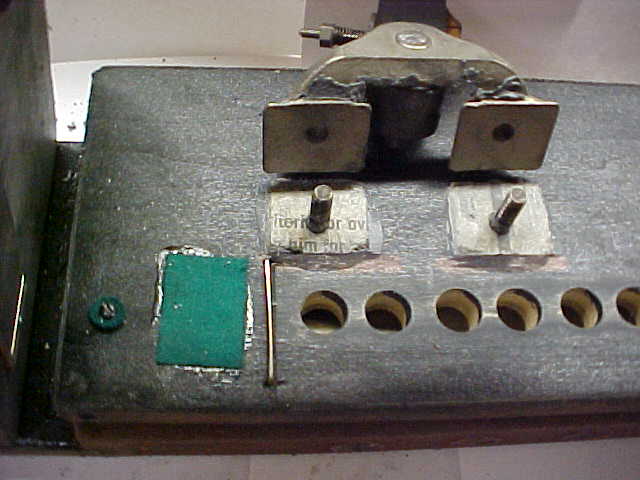
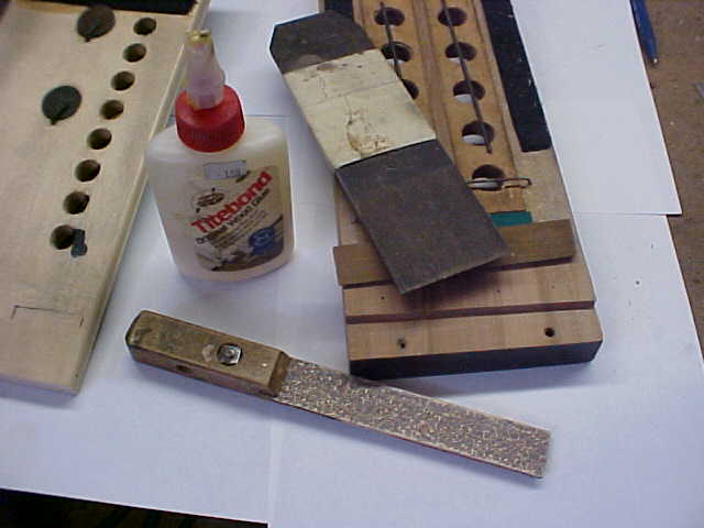
PHOTO A5 Masking the foot Use a Dremel tool to mark each foot with a number corresponding to the number on each feeder. Also stamp numbers on each arm just in case the holes drilled for the bushings are not true. It is a good habit to index parts so they go back together just the way they came apart. The first step in realigning the pump arms is to mask off the area around the foot impression using masking tape. Remove the flap valve. Tack two layers of newspaper onto the bottom of the foot with as small a quantity of Titebond glue as possible. The newspaper will enable you to remove the foot at the end of this process. Wrap the bolt threads with Teflon plumbing tape so that the epoxy does not stick to the threads. (NOTE Re: GREEN FELT: Ampico used a great deal of this green cloth. This is simply pool table felt. It is called felt but it is actually woven cloth and can be torn just like bushing cloth). |
 |
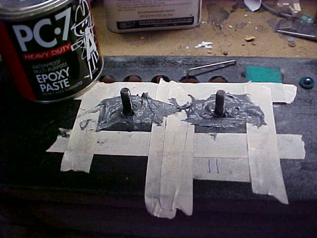 |
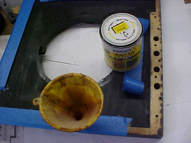
PHOTO A 6 Applying epoxy PC-7 is a paste type epoxy that is very hard after curing. Wrap the bolt threads with Teflon plumbing tape before applying the epoxy. Apply as small a quantity of epoxy as possible. It looks like I have a used a lot of epoxy but that is not the case. Apply enough epoxy to level the impression plus a little extra to give you some room for an adjusting the tilt of the wooden arm. Before applying the epoxy take note as to where the wood is depressed. If there is no depression on one side of the foot do not put any epoxy on that side. The goal is to level the foot, not to raise it. Be careful not to get epoxy on the threaded bolts as it is possible to epoxy the foot permanently to the bolts. If you have never used this method, level only one foot just to make sure that you do not epoxy the foot to the threaded bolt. |
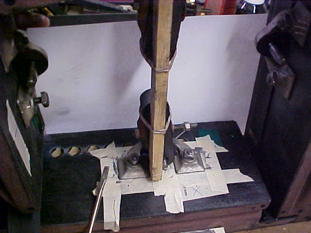 |
PHOTO A7 Foot clamp The foot is set into the epoxy and the two bolts are hand tightened. The bolts are tightened a little bit more by hand and the epoxy is pressed out along the sides of the foot. This operation takes some judgment. Remember you don't want to raise the foot higher than the factory intended it to be. When you are satisfied that the foot is at the correct angle, scrape all the excess epoxy from around the foot. Then place a stick on the two opposing arms with a rubber band around each arm. This will insure that the arms remain in alignment with one another while the epoxy is setting. |
|
PHOTO A8 Foot removed showing newspaper The epoxy has set overnight and the foot has been pried up revealing the newspaper. A good bit of force was needed to break the bond between the newspaper and the foot. This is why you want to apply as little glue as possible to the newspaper when tacking it to the foot. I placed a thick putty knife level with the wood and used a screwdriver to pry the corners of the foot loose. The putty knife protected the wood from becoming marred from the screwdriver. I pried the foot off on the opposite side of the flap valve so as not to take any chance of harming the flat surface the flap valve seats against. After I gained a little leverage, I worked a thin putty knife under the foot to pry it loose. The excess putty was then leveled off with a chisel. In this case the epoxy is almost level with the original surface of the wood. If Ampico had used maple for the plywood layers of this pneumatic, this problem would not have occurred. |
 |
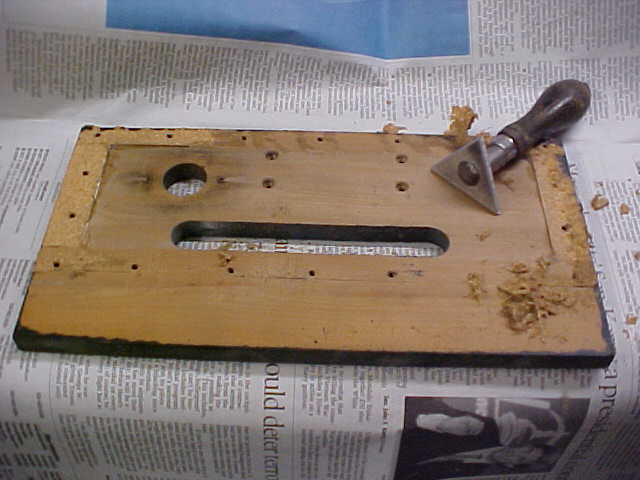 |
PHOTO A9 Distributor base Ampico does not give this board a name in the Inspector's Reference Book and so I'm going to call it the distributor base. It is the board located at the top of the pump to which the distributor block is screwed down to. This board is most likely Red Gum wood. The board has been turned upside down. You can see in the photo the hole for the spill valve and the four screw holes for securing the amplifier pneumatic. The long slot brings pump vacuum from all four feeders into the distributor block. Also in this photo you can see a triangular scraper. This was originally a paint scraper that I bought 30 years ago. I use it for cleaning wood. It was made with a tempered blade. I sharpen this on my belt sander. I use it for heavy work, so there is no need to keep a fine edge on it. I have gone through four of these blades in my career. I have tried to replace this tool but the new scrapers I have purchased are made from inferior metal so I have included plans of this tool in this writing. The blade should be made from tool steel. The blade I am currently using was made by Bob Streicher. Note that this is a very dangerous tool. You can cut yourself very badly with it. I would suggest that only someone who considers himself a skilled craftsman use this tool. I prepare as much of the wood by hand as possible. In this case I do not take the distributor base to my belt sander to remove the gasket. This board has conformed itself through the years to the configuration of the board which it mates to. Sanding on a machine would disturb its seat. Removing old material by hand is a good way for you to practice your craftsmanship. The gasket should be removed as well as the glue, but almost no wood should be taken off in preparing the wood. I've worked on too many machines that had been previously restored where someone sanded the pneumatic boards too much, taking them out of square and changing their dimensions. A power tool will amplify your errors. If you are a new restorer, buy a belt sander with a four inch wide belt. A narrow belt will put digs in the sides of large pneumatics. The last step in reassembling the pump is to screw down the distributor block to the base board. More often times than not, one or more screw holes will strip when tightening down the distributor block to the base. You can't use toothpicks to secure these holes because there is a chamber directly underneath the distributor base for the underside of the top flap valve. If a tooth pick or a wood fragment were to lodge itself under the flap valve creating an uneven seat, the pump could loose a great deal of its power. To avoid the situation of stripped screws I make sure the screw holes are strudy to start with. The first step in securing the screw holes is to clean the old cork gasket from the distributor base. The cork gasket is going to be replaced with packing leather. I make index marks on the wood to indicate the size and location of the new gasket. Ampico used cork as a gasket material throughout the player mechanism. I replace all the cork with leather except the following: (a) the gaskets in between the stack tiers (so that I keep the spacing the same as original and so the next restorer can take the stack apart); (b) the primary chest (so that I keep the spacing original); and (c) the secondary valve gaskets. Never use cork that comes pre-glued. Pre-glued cork turns gummy over time and the gummy adhesive is difficult to remove from the wood. |
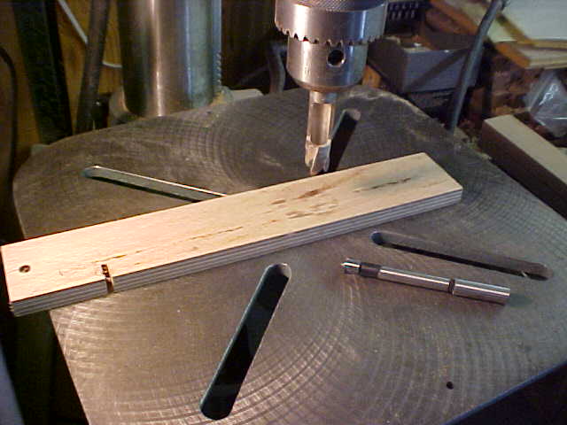 |
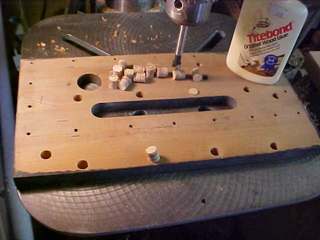
PHOTO A 10 Making plugs We are going to make twelve plugs for the twelve screws which hold down the distributor block. Here you see everything you need to make the plugs. The three eighths inch forstner drill bit is laying on the drill press table. Forstner is a type of drill bit that will allow you to make flat bottoms in the new holes. The self ejecting plug cutter is secured in the drill press chuck. It has a hollow center so the plugs are forced up and are ejected out the top. The wood in this photo is a scrap of Dilignit pinblock material. Dilignet is a brand name. It is considered by most piano rebuilders to be the finest pinblock material made. Each laminate is about one sixteenth of an inch thick and is glued together under pressure. This makes for a very stable, very strong material. It is expensive to buy a plank of Dilignet just for this process. When a pinblock is cut to size and shaped there are always trim pieces left over, so take a trip to your local piano restorer and ask him for some scraps. If you have to pay for a scrap, that's fair because he wants to use the scraps as much as you do. A good woodworker can make many functional parts using this wood. |
|
PHOTO A 11 Setting the dowels Place the distributor base right side up on your drill press. Using a small bit, drill through the center of each screw hole to mark the centers on the opposing side. Then turn the board over as in this photo. I have the forstner bit in the drill press and I have the stop on my press set so that the hole is not drilled all the way through. Leave a thin layer of wood about 20 thousandths thick in the bottom of the hole. This makes for a neat job and does not change the appearance of the top surface of the board. I drill out ten of the twelve holes leaving two holes as indexes for locating the junction block. Leaving two original screw holes at each end of the distributor will enable you to mark the centers for all of the screws when it's time to drill pilot holes for the screws. Glue the new plugs in with Titebond glue. After the glue has dried, use a chisel to shave the dowel even with the surface of the board. |
 |
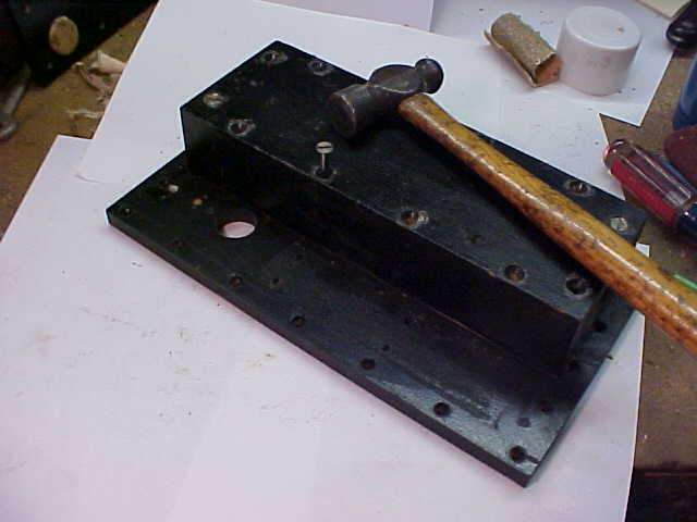 |
PHOTO A 12 Marking the centers The two screws which still have their original holes are the ones screwed in. This locates the junction block in its original position. Place a screw in a hole where a new plug is located and tap the top of the screw lightly with a hammer. Turn this screw 90 degrees and tap again. You have now marked the center of the plug for drilling. Mark the centers on all of the new plugs. After the ten new plugs have been marked drill them with the proper size drill bit to make pilot holes for the screws. Remember not to drill the pilot hole all the way through the board. After you have done this you can plug the two remaining holes that you used as an index. |
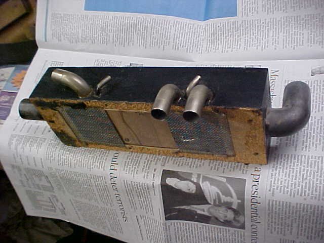 |
PHOTO A 13 Distributor block, bottom view This is the bottom of the distributor block. The elbows are going to be removed. Before removing the elbows, mark the wood with a light impression underneath each elbow to indicate the angle of each elbow. It is important when replacing the elbows to get them facing in the proper direction. In this way you will not have to remove the pump from the piano to change the direction of an elbow when re-tubing. In the center of the distributor is the cut off pouch. This pouch stops the stack from playing while the roll is rewinding. |
|
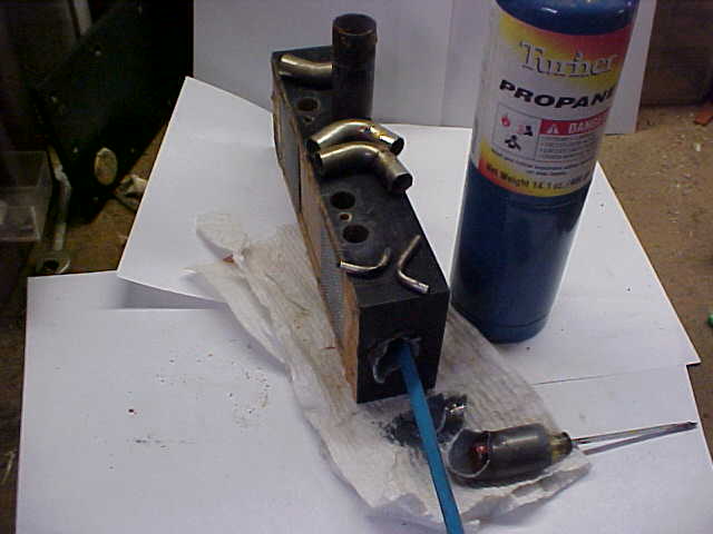
PHOTO A 14 Removing the elbows from the distributor. The elbows are going to be removed so they can be resealed with freshly mixed shellac to insure an airtight seal. Use a propane torch to heat the elbows. The heat will soften the old shellac to enable you to remove them without force. Whenever you have trouble removing a nipple or elbow, always apply heat. This method is very helpful in removing the reducing nipples for signals one and five on the crescendo units. Sometimes the distributor block breaks next to the elbow for the cut off pouch. If this happens don't glue the wood until you are ready to reinstall the elbows. Apply glue to the break, install the elbows with shellac and then clamp the distributor block to secure the break. I was not able to remove the old lead elbow shown in the bottom of the photo. I tried to loosen it by placing the handle of a screwdriver in the end, using the screwdriver as a lever. I broke the elbow off and so now a hack saw blade is being used to cut the elbow for removal. All the lead in the player mechanism will be replaced. This elbow will be replaced with a brass elbow. The replacement elbow will be trimmed so that it extends out and up to the exact points of the old lead elbow. Place the elbows in a container filled with a diluted solution of ammonia to clean them. The ammonia removes the shellac and takes off all the tarnish, saving the original plating. If the ammonia solution is too strong it will remove the plating in just a few minutes. Make the solution weak enough so that the parts can soak for at least a couple of hours without affecting the plating. Try a solution of two parts amonia to one part water. The ammonia solution can be used to clean many parts such as valve caps and all the elbows and nipples throughout the mechanism and transmission parts except for fiber gears. |
 |
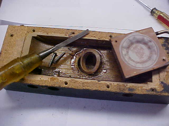 |
PHOTO A 15 Inside of the distributor block In this view the screens have been removed and the cut off pouch has been removed and turned upside down. I always break the cut-off seat out of the distributor so that it can be re-glued. They are set in place with flake shellac but I set them back in with Titebond glue. The rings are usually easy to get out. Often times you will find a crack in this ring. If the ring has shrunken you can add a piece of veneer to repair the crack. The cut-off pouch will be recovered using pouch leather that is about fifteen thousandths thick. Thin leather on this pouch would be inappropriate as it has heavy work to do. This pouch will be sealed with diluted rubber cement and treated with talcum powder. |
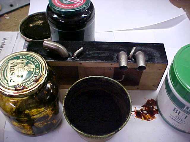 |
PHOTO A 16 Distributor block shellac In this photo the distributor block has been repainted and the elbows have been reinstalled with flake shellac. When an elbow is placed into a player component it must be sealed so that it is airtight. Originally, shellac was universally used for this purpose. If you use flake shellac to seal the elbows, they may be repositioned by applying a slight amount heat. The original shellac used by the factory is called burnt shellac. The factory would remove the lid from a can of shellac and set fire to it. Shellac is alcohol based so the fire would burn off the alcohol and eventually the shellac would get thick and dark in color. In the lower right hand side of the photo you can see a container of flake shellac. Some flakes have been removed to show what they look like. Flake shellac acts and looks exactly like the burnt shellac. To make flake shellac you simply place some flakes in a container and cover them with alcohol. Make the shellac a couple days ahead of time because it takes a while for the flakes to dissolve. You can thin the consistency by adding alcohol. To thicken the solution you can add more flakes or you can leave the top off the container to allow the alcohol to evaporate. You cannot store flake shellac in a metal container because it would get contaminated by rust. The best container to use is be a glass preserving jar. I usually paint Ampico components with black lacquer from a spray can. But sometimes I brush on black shellac. Black shellac comes in handy when you have to make a new piece of wood pitch black. It's the only practical way to go from a light colored piece of wood to dark black. One coat will usually do the trick. Most player components were originally finished using black shellac. To make black shellac, you simply take a can of shellac and mix in black powdered dye that is soluble with alcohol. |
|
PHOTO A 17 Distributor dust screen If you restore the bottom of the distributor block exactly as it was you will have problems getting the distributor block gasket to seat. This is due to the fact that a screen is placed underneath the gasket. The metal screen will not allow the new gasket to lay flat, and so the mating surface will be uneven. This unit had a cork gasket that is being replaced with packing leather. This dust screen is,in my opinion, useless in a restored mechanism. Its purpose was to keep large particles from getting underneath the flap valves in the pump. A carefully restored mechanism will not have large particles in the system. Particles under the pump flap valves will cause the pump to lose a great deal of power. Do not replace the screen with a finer mesh material. Lots of air passes through the screen and a finer mesh material would soon get clogged with lint and stop your piano from operating. The metal screen will be replaced with nylon screen of the same mesh size. I replace the original tacks with bridle strap tacks. Do not glue the screen to the wood. Glue the new leather gasket on top of the screen with fish glue. Before the glue sets, brush on a thin coating of flake shellac to the exposed side of the gasket and screw the distributor block to the base board. In this way you will end up with a very flat surface that will easily make a good seal.
I use two methods for making gaskets. In this case, the gaskets were made oversize to extende over the edges of the wood. After the glue had set, the excess leather was trimmed with a single edge razor blade to make a clean edge. To mark the holes, lay the leather in place and press down on the leather over the holes with the handle end of a small screwdriver. This makes an impression in the leather and marks the holes for punching. This make an accurate gasket and the wood is not marred by an Exacto blade. The second method for making complex gaskets will be discussed in section "D 14". |
 |
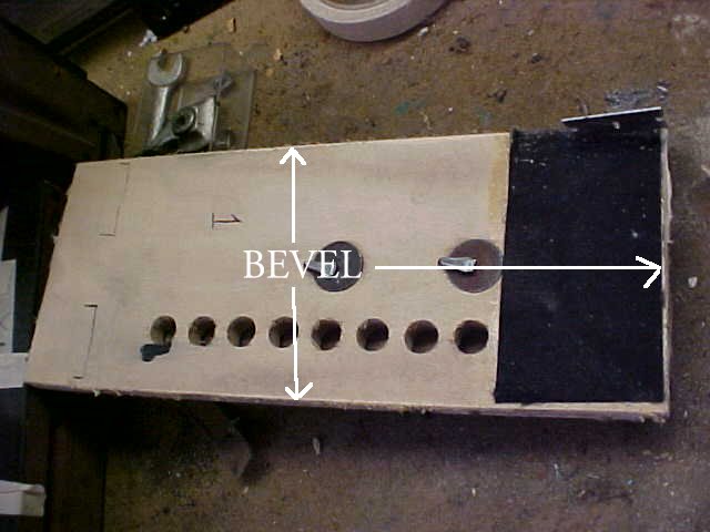 |
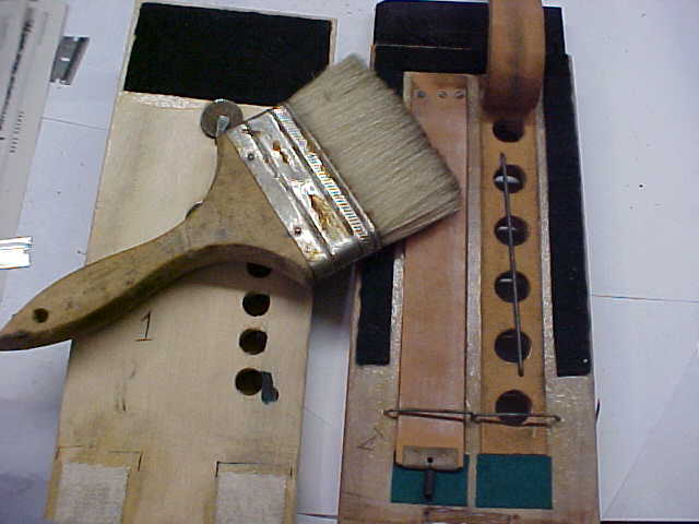
PHOTO A 18 top feeder inside Remember when we repaired the foot of the pump by using epoxy? This is the reverse side of that board. It is the movable leaf of one of the four pump feeders. Mark the location and width of the hinge material with ink. Then clean the board of its hinge material. Trim the black felt so that there is about an eighth of an inch clearance to the edge of the board. Bevel three sides of the board with a hammer file (Schaff Piano Supply) so that when recovering the feeder, the excess glue on the cloth will end up in this beveled area. In this way the span of the pneumatic is not reduced. Do not bevel the hinge end of the feeder board. |
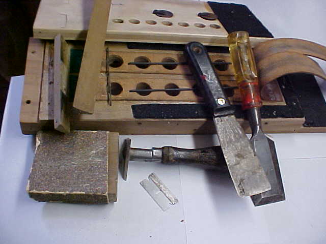 |
PHOTO A 19 Feeder bottom If you look at the sides of these boards you will notice they have been prepped for recovering. All this work has been done by hand. Once again I stress workmanship over speed. A power tool such as a belt sander will only amplify your errors. Removing all the old cloth and glue by hand allows great care. There should be no removal of wood in this process apart from some dust. All the tools necessary to prep the pump are in this photo. I use the triangular scraper to remove most of the material. I use the chisel to remove the glue from the hinge end of the pneumatic, a razor blade to trim the felt, and a wood block with 40 grit sandpaper for the final sanding. The putty knife is used to remove the triangular hinge spacer. It took me about forty minutes to clean this one pneumatic. It has been returned to the same dimensions as it left the wood shop in the factory. |
|
PHOTO A 20 Cleaning the flap valves One of the inner flap valves has been pulled back for cleaning. I use a dry paintbrush to clean any debris from the flap leather. A piece of debris on this leather will cause a great loss of the pump's power. I use my experience to determine whether leather needs to be replaced or not. There is no test to tell whether leather should be replaced or not. If you are not sure if leather is going to last you may choose to replace it. |
 |
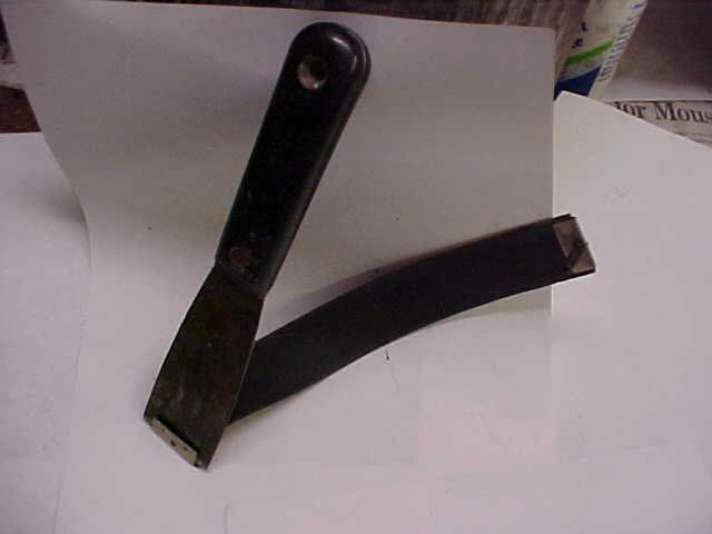 |
PHOTO A 21 Replacing flap valve leather Use a thin putty knife to force the metal clasp at the end of the flap valve open and remove the old leather flap. Clean the inside of the clasp and prepare to cut new leather. Select a skin of similar thickness that is smooth on the show side and has a fine nap on the seating side. Test the leather by pulling it. Just like pneumatic cloth, leather will tend to pull more in one direction than another. Determine which way the leather stretches the least and use that for the length of the valve. Always choose the tautest direction to use for the longest measurement of cloth or in this case a flap valve. |
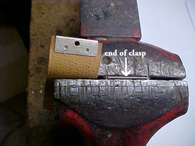 |
PHOTO A 22 Clamping the valve in the clasp The left side of the photo shows a clasp on a new flap valve. There is an end of a clasp in the vise. Pre-punch a hole in the leather to match the hole in the clasp. Squeeze the end of the leather with a pair of wide pliers to bring the end of the leather to a point. This tapers the leather so that it can be forced into the very end of the clasp. Brush a very thin coating of Sobo glue or fish glue on the end of the leather to secure the leather to the inside of the clasp. Place the clasp in a vise making sure not to squeeze the bend of the clasp. The end of the clasp stands just above the top surface of the vise jaws. If you squeeze the bend of the clasp, this will tend to open it. When reinstalling the flap in the pump, check the length of the new flap making sure the coil spring has enough room to stretch about an eighth of an inch or so when the screw is inserted in the old screw hole. |
|
PHOTO A 23 Re-gluing the wood hinge Most Ampico pneumatics, apart from key pneumatics, have a triangular piece of wood at the hinge. This piece of wood allows the cloth on the sides of the pneumatic to tuck in so that the pneumatic does not bind at the hinge end. I always re-glue all of these spacers using Titebond glue because there is no need to remove them for the next restoration. Ampico pumps are known for making noise. Once the pump arms have been serviced the only other source of noise is this triangular piece of wood at the hinge end of the feeder. This piece of wood at the hinge is what causes Ampico pumps to make a thumping noise. More often than not the glue that holds this piece of wood to the body of the pneumatic has failed. Re-gluing this board will insure against the pump making a thumping sound. Even if the glue joint is solid, always break these boards out and re-glue them just in case the glue joint decides to fail ten years from the point of restoration. In this case the glue joint was positive and the triangular board was destroyed during removal. If the triangular board pops off easily the old glue should be thoroughly removed on both sides of the joint and then re-glued using the original nail holes. I keep replacement boards in stock. It only takes a few minutes to rip a strip of poplar on a table saw to make a replacement. Notice that the top of the triangular board has a slight flat on it at its highest point. Sand the glue off the old joint with a wood block or a hammer file. These files come in handy and are very inexpensive. The large rectangle resting on top of the pneumatic is a blade from an old wood plane. This is a special serrated blade. I have drawn a rough diagram that you will find at the end of this writing. The head should be made of tool steel. A brand new miter saw or small Japanese joining saw can be used instead, by laying the saw on its side, and drawing the sharp teeth over the wood surface. Whenever I want to make a good glue joint, I use this blade to score both wood surfaces. Scoring the wood makes a good mechanical bond for the new joint. These very same score marks can be seen on many old glue joints, not just in piano work but on antique furniture that was assembled with hot glue. Teflon is known for being a non-stick surface, and yet the makers of skillets are able to get Teflon to stick to aluminum pans. This is accomplished by oxidizing the aluminum surface. When the Teflon is applied to the oxidized surface it is locked in place by the irregularities of the oxidized surface. Scoring is also used in the pottery trade. When two pieces of clay are joined together they must be scored to make a good bond. I also use this scoring principal when I prepare leather for valves. I lay valve leather nap side down on the resurfacing glass and lightly sand the gluing surface with 100 grit sandpaper. I also attach my valve disks to pouches using this principal which will be shown in another section of this writing. If you buy replacement valve discs from Player Piano Company made of glossy fiber the gluing surface must be sanded to make sure the leather adheres to it. |
 |
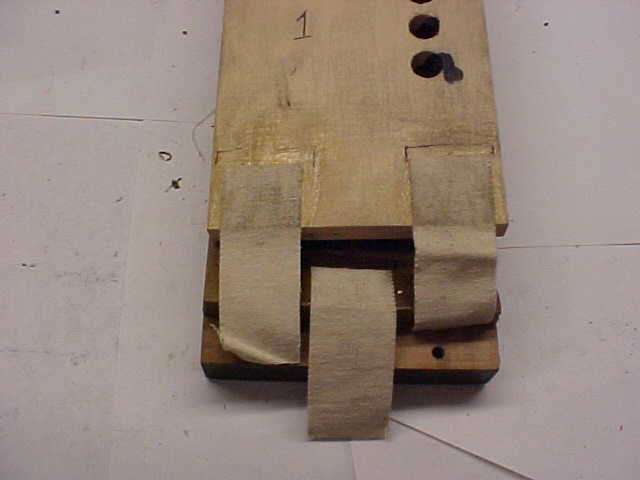 |
PHOTO A 24 gluing the hinge cloth This is the next step in restoring the hinge. The new hinge is made from heavy canvas cloth approximately 20 thousandths thick, purchased from an art store such as Dick Blick. This cloth has the appearance of a twill weave. The hinge cloth is glued down with hot glue. Make sure the material is securely glued on the outside edge of the pneumatic. For medium size pneumatics Dick Blick sells a lighter weight canvas. For smaller Ampico pneumatics with overlapping hinges of this type covered in motor cloth such as the expression regulators and shut off pneumatic, use cotton cloth with the consistency of a bed sheet. For key pneumatic hinges, punch circles from pneumatic cloth. |
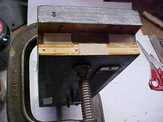 |
PHOTO A 25 Gluing the hinge cloth Use a "C" clamp to hold the two halves of the feeder pneumatics in the final process of re-hinging the feeder hinge. The clamp is gently, but firmly, holding the two parts of the feeder together. This insures that there will not be any play in the hinge. Play in the hinge will also cause a knock. Secondly, the "C" clamp will allow you to align the two boards for recovering. The hinge cloth is glued with hot glue. Use a wet (water) putty knife to work the cloth tight in either direction. Wetting the knife will not let the glue stick to the knife. Then trim the excess cloth with a single edge blade. |
|
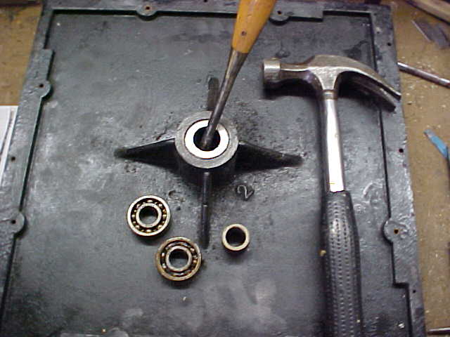
PHOTO A 26 Removing the front bearings Ampico pumps contain four ball bearings. It is best to replace these to reduce noise. Sometimes the races or tracks that the bearings ride in are worn. The old bearings were not made as well as the replacements. This is the front of the pump turned with the inside facing upwards. This front is a single piece of cast iron. Use a three eighths inch punch to remove the old bearings. A heavy screwdriver can also be used as long as it has a metal blade that extends through the handle. Quite a bit of force is necessary to pound the old bearings out of the casting. Put a few drops of penetrating oil on the edge of the old bearings to help the job along. There is a spacer in between the front and back bearing that must be put back in. Once this process is started there is no turning back. The old bearings will be damaged with the first blow. |
 |
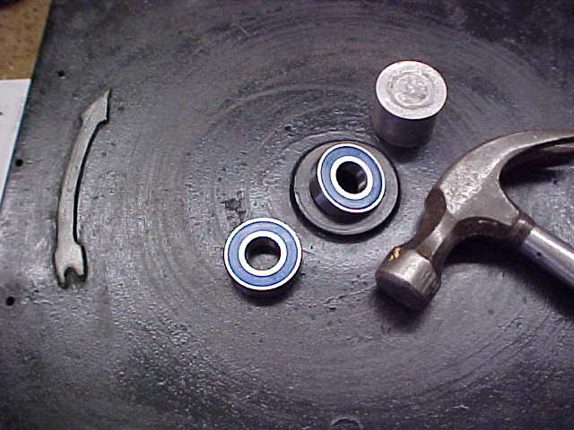 |
PHOTO A 27 Replacing the front bearings Care must be used when installing the new bearings. Striking them directly with a hammer would ruin them. Pictured just above the hammer head is the aluminum cylinder I place over the bearing for striking. This cylinder is just undersized to the diameter of the bearings. Force the bearing in evenly so that it does not get cocked in the hole. |
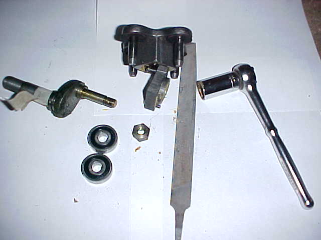 |
PHOTO A 28 Removing the spider bearings This is the unit that contains the rear pair of bearings in the center of the spider. To access these bearings, remove the access cover from the unit. Use a file to make an index mark so that the cover will be put back in the same position. Next, the hex nut must be removed. The hex nut is threaded backwards so that it remains tight while the pump is running. To undo this nut, turn it in the direction as though it were being tightened. These two bearings are easier to remove than the bearings in the front casting. |
|
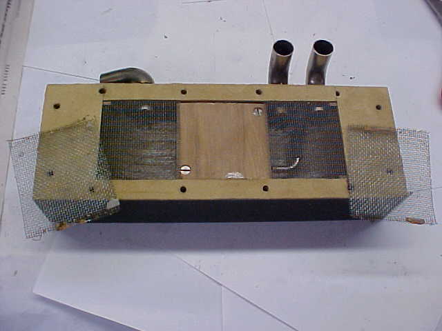
PHOTO A 29 Sealing the back pump cover This is the very back of the pump. The vacuum produced by the four feeder pneumatics will pass through this hollow cover. These covers are known for being porous. Mask off all the holes on the inside of the cover except for one. Vacuum the inside of the cover to remove lead dust. Each feeder pneumatic is held on to this cover by seven screws. Sometimes the factory drilled one or two of these holes incorrectly and they intersect the hollow portion of the cover. This will cause the pump to leak at the slightest drop in humidity. Test the cover to see if there is a leak on the show side of the cover through one of the 28 screw holes. If this is the case, buy a brass tube at a hobby store with the same inner diameter as the original screw hole. Drill the hole in the cover out larger and force fit the brass tube into the hole. This will isolate the screw hole from the hollow area of the back cover as it should be. Seal the inside of the cover by pouring in watered down Titebond glue or fish glue. All the passageways in this unit are very large and so glue can be used to seal it rather than shellac. Flake shellac is pictured here because I want to caution you not to use glue to seal other channels. This is the only time I use glue when sealing part of an Ampico. Make sure to pour the glue out right away. Any liquid left too long in a chamber can cause the old glue joints to pop. I have never had trouble with a back cover coming unglued during this sealing process, but I have run into other situations where this was so. After the sealant has been drained, cut out the sixteen large holes in the masking tape and turn the cover upside down to make sure all the sealant runs out. Do not remove the tape just yet or the sealant will get on the newly sanded wood where the old cork gaskets used to be. The cork gaskets will be replaced with packing leather. They will be glued in place as the cork was. Do not glue or shellac the mating side of the gasket when screwing it back in place. That would make it impossible to remove the cover in the future. |
 |
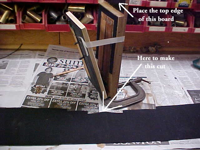 |
PHOTO A 30 Recovering feeder This is the first step in recovering one of the feeder pneumatics. Recover the feeder with Stayfast cloth. Stayfast is a rubberized cloth made for Mercedes automobile tops. The show side of the cloth is synthetic and the underside is mostly cotton. After the glue has been applied and the cloth is in place, use an iron to heat the cloth to force glue into the weave. Once again this will form a mechanical bond between the glue and the weave of the material and the cloth will be fixed in place. (Because this cloth contains synthetics, I never use Stayfast when recovering pressure pumps). Place the feeder on end using a "C" clamp for a stand. The total span of the feeder pneumatic is five and a half inches. Place a piece of masking tape along side to hold the pneumatic open five and five eighths inches as in the photo. The black Stayfast cloth in the front of the photo has been cut oversize at six inches. Cut about a quarter of an inch off of the near side (about a foot wide)with a straight edge, we'll call this the A side. Then carefully measure five and a half inches from the A side and trim the other side of the cloth, the B side parallel to the A side. Make the B side cut also about a foot across. Place the stationary part of the feeder (the side containing the flap valves) on top of the cloth (as arrows indicate on the A side) to make a custom fit cut out. This is the only time I use the span of cloth to determine the opening of a pneumatic. The longer pneumatic board that contains the flap valves is made from solid wood rather then plywood. The portion that is going to be covered first is end grain. The end grain will absorb a lot of glue. It is best to seal the end grain with a coat of hot glue. Brush on some hot glue and let it set. Then follow up with two more coats of glue when attaching the new cloth as described in section A 33. |
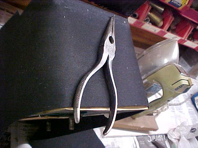 |
PHOTO 31 A covering feeder end Notice the iron in the background of the photo. Tacks are used only to speed up production they are not used to hold the cloth on. Use very few tacks when recovering the feeders and the reservoir. Tacks are very helpful on the hinge end to get the cloth to seat around the hinge material. I end up using about as many tacks on the hinge as the factory used. If you are working on a pump in original condition, I would suggest reusing the copper tacks. Most of the new tacks are wider near the head then the original tacks. This can cause the wood to split. To split a log in half, a metal wedge is used. The plywood on the feeder pneumatic and the hinge can easily split if new tacks are used. The name of a supplier and the size of good replacement tacks are listed at the end of this writing. Unfortunately, the company's minimum sale is $25 worth of tacks. Often the movable leaf shown in the bottom of this photo is warped. If this is the case, line up the outer edge of the cloth with the center of the movable leaf. |
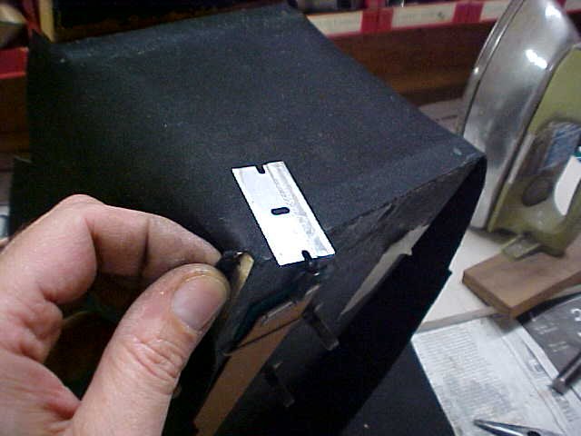 |
PHOTO A 32 Cutting the corner This is a method I use when recovering all size pneumatics. The cloth is cut in about one third the thickness of the wood. If this is not done it will be hard to get the cloth to sit flat on the wood at this point. |
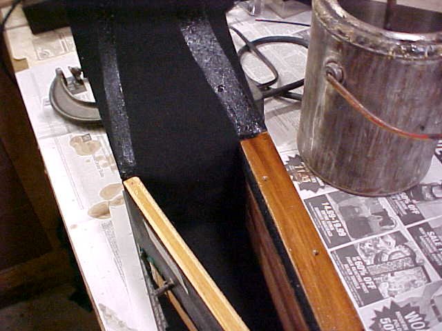 |
PHOTO A 33 Gluing and ironing Due to the heavy weave in bellows cloth, two coats of glue are needed. One coat will get absorbed into the cloth and there will not be enough glue left to secure the cloth to the wood. This photo was taken after one coat of glue was applied. The cloth was peeled back and another coat was applied to the cloth over the first coat of glue. After the second coat of glue is applied, iron the cloth to work the glue into the weave. If glue starts to run down the sides of the feeder it is because you applied too much glue. When gluing all types of pneumatics you should see beads of glue squeeze out the sides with dry spots in between. This is an indication that just the right amount of glue has been used. Another rule is: the heavier the cloth, the thicker the glue. The average texture for hot glue should be the consistency of honey on a warm day. |
|
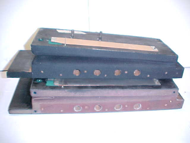
PHOTO A 34 Completed feeder In this photo the restored feeder is on top of the unrestored feeder. The holes are cut out using an Exacto knife. The holes must be cut out after the glue sets but before it hardens. The cloth should also be trimmed before the glue hardens. The holes should be cut out about a half an hour after recovering. Always recover the fronts and the sides of all pneumatics and let the glue dry overnight before recovering the hinge or you may not be able to fully open the pneumatic. The fronts of the feeder pneumatics can be folded in the usual manner. The only advantage to folding cloth the way the unrestored feeder cloth is folded is when the span of a pneumatic is great. Pneumatics on upright Ampico motors are folded the same way as on the unrestored feeder for this reason. |
 |
|
The photos in this section are not in the order that I restore a pump. Here are the steps to go through in restoring a pump in sequential order: 1. Stamp numbers to mark the feeders and feeder covers 2. Mark the back cover with an arrow to indicate the top surface 3. Stamp numbers on each pump arm 4. Restore all pump components 5. Assemble the four feeders and attach the front casting 6. Align the pump arms 7. Assemble the pump |
|
on November 8, 2022 by John A. Tuttle, who Assumes No Liability For The Accuracy or Validity of the Statements and/or Opinions Expressed within the Pages of the Player-Care Domain. This page was last revised on December 18, 2024. |
|
407 19th Ave, Brick, NJ, 08724 Phone Number 732-840-8787 (Voicemail Only, No Texts) |
