
|
|
|
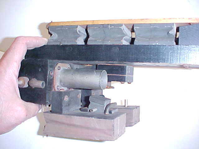 |
PHOTO D 1 Unrestored expression mechanism spring pneumatic side |
|
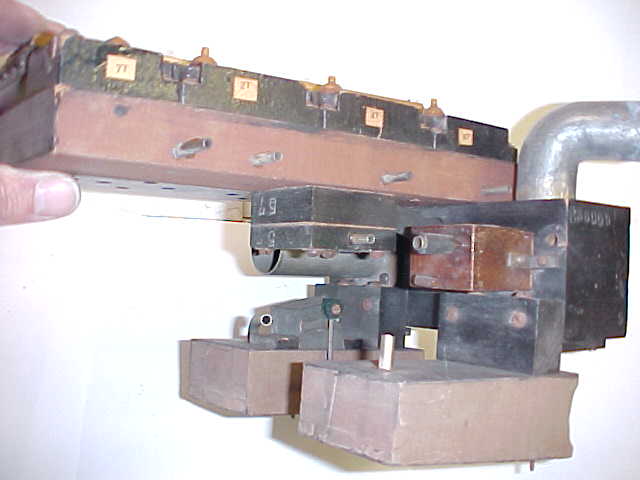
PHOTO D 2 Unrestored expression mechanism subdued pneumatic side |
 |
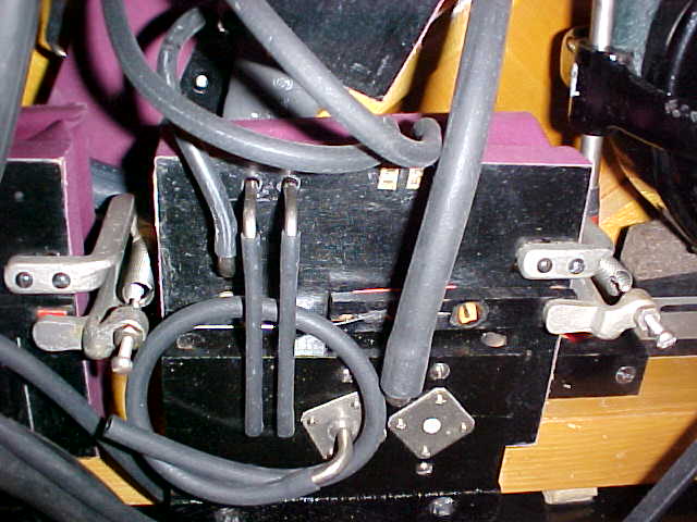 |
PHOTO D 3 Crescendo This is a photo of a crescendo unit in a 1923 Knabe grand piano. Ampico components are installed differently from one grand to the next. |
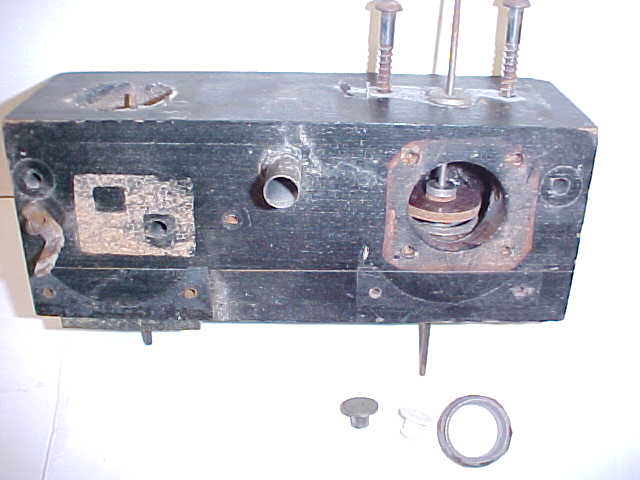 |
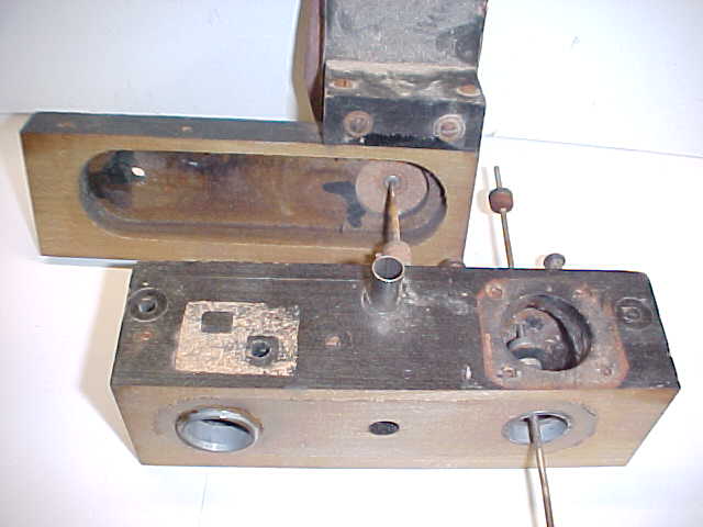
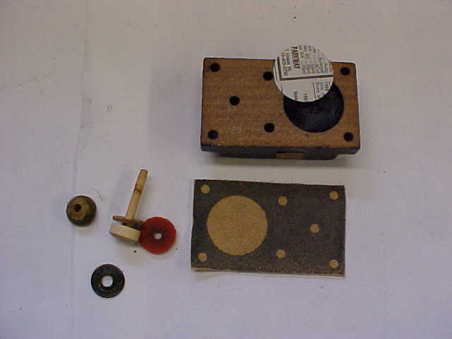
PHOTO D 4 Expression disc This is the main body of an expression mechanism that I found in my parts department. Most of the useful parts have been removed to restore other mechanisms. The left side of this box is controlled by the subdued switch. The hole on the top of the unit on the left connects to one side of the stack. The right side used to have a straight nipple one and an eighth inches in diameter. The right side of the box receives its vacuum from the pump through this nipple. Inside the opening on the right is the heart of the Ampico "A" expression mechanism. It is simply a disc which floats above a metal seat. |
|
PHOTO D 5 Expression box opened The expression box has been opened for purposes of demonstration. It is never necessary split a box open in this manner. Vacuum is introduced to the right side of the box from the pump. As the disc lifts off of its metal ring seat, vacuum passes through the lower chamber, through the subdued section of the box on the left and then up to the stack. This photo gives a good view of the metal ring seats. The ring seats are nickel-plated brass. Always remove the ring seats both on the expression side and on the subdued side and secure them back in place with fresh flake shellac. Most of the time the ring seats are ready to fall out. If vacuum leaks past this ring the expression will be affected on soft playing. Resurface both ring seats and spray them with brass lacquer. The disc floats the moment the Ampico is turned on and therefore it never seats on the ring while expressing. It is important to treat the top of the ring with lacquer as the leather on the disc rests against the ring all the while the Ampico is not in use. If the metal ring seat is not treated with brass lacquer, the leather on the disc will corrode the seat. Early mechanisms used aluminum discs, later mechanisms used fiber. Sometimes the fiber discs are warped. If this is the case send the warped disc to a machinist and have a new disc of the same dimensions made out of aluminum. Resurface fiber discs on the leather side only. Never resurface the slick surface on the upper side of a fiber disc because the disc would warp over time. Replace the leather on the disc using leather with the same characteristics as the original. I use upholstery leather supplied by Bill Hirsh antique auto restoration supply. I also use upholstery leather for making gaskets for the four primary type block valves on each expression unit. Replace the metal bushings that the expression rod rides through. Sometimes the metal rod makes a squeaking noise as it rubs against the metal bushing. The new Teflon bushings will eliminate this noise. Place the old bushing on your bench with the large ring face down. The hole is not the same diameter all the way through the bushing. Run a drill bit into the end and take note that there is a larger hole drilled out most of the way through. There is a smaller diameter hole on the face of this bushing that nearly matches the diameter of the rod. Check to see that the new bushing is drilled in the same manner. If it is not you must use a numbered drill (the 1 through 60 drill set) to drill out the Teflon bushing to match the original. If the Teflon bushing is not drilled out to match the old bushing the expression rod will bind. Place the expression rod on the resurfacing glass. Prop one end of the glass up slightly and see that the rod rolls down the glass. This is a test to see if the rod is bent. After the new bushings have been installed and the rod has been straightened, use the threaded portion of the rod to ream the end of each new bushing. Make sure the expression rod falls through both bushings on its own weight. Install the ring seats with flake shellac. Then install the rod and the disc making sure the disc has enough play in it so that it may seat against the metal ring seat. A chart is provided at the end of this writing to help locate the position of the rod and its components. |
 |
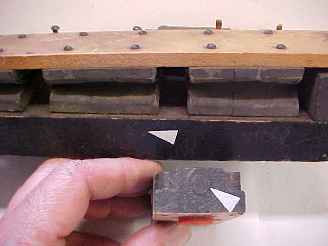 |
PHOTO D 6 Sealing plugs There are many channels in the expression unit. In order to create these channels the factory had to drill through the sides of the wooden parts. The factory then used dowels to plug the ends of the channels. The plugs shrink over time and must be resealed. On some expression units, the factory placed pneumatic cloth punchings over these plugs. The factory used burnt shellac to attach the cloth punchings and the original cloth punchings often come loose. To improve this situation a different approach must be taken. Hot glue cannot be used on a shellacked surface. Instead use Sobo glue to attach new cloth punchings over every plug. Sobo will not get into the wood because the surfaces are shellacked. I'm holding one of the expression valve blocks in my hand. I re-use the felt punchings (action cloth) on the bottom of these units. This old felt has been packed down, which is a good quality for this use. If you decide to make new punchings use thick action cloth. Before installing the new action cloth punchings strike them with a hammer to compress the felt. |
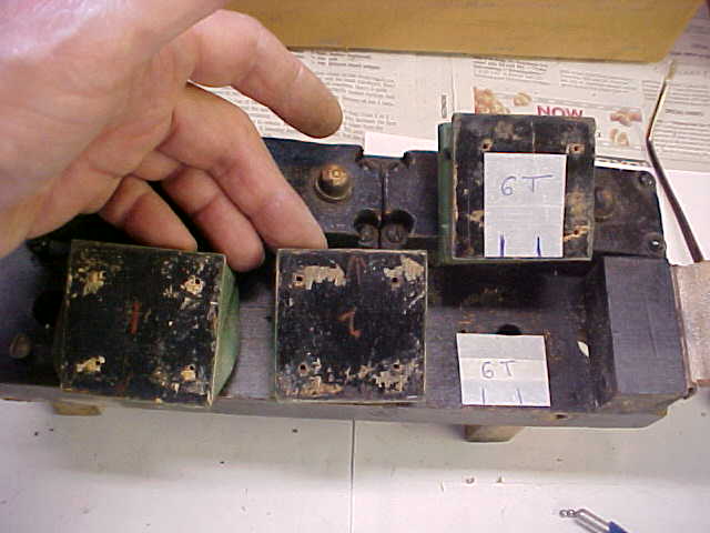 |
PHOTO D 7 Marking intensity pneumatics As you can see in this photo, the previous rebuilder was not careful in marking the intensity pneumatics and so they did not go back in their proper places. Notice on the center pneumatic, the number 2 is upside down. Step 1: After removing the common lever board on top of the intensity pneumatics, mark the tops of each of the pneumatics with the corresponding intensity numbers 2, 4 and 6 and a letter "B" or "T" for bass or treble. Number 2 pneumatic is always closest to the fulcrum. Then mark two lines to indicate which side the overlap is located on. The overlap always faces toward the outside as indicated. I have applied masking tape so the marks would show up in the photo. When marking these pneumatics, use a ball point pen and press hard to leave a impression. This way there will be no chance that the markings will rub off during the recovering process. The lever board will cover up these impressions when the expression unit is reassembled. Step 2: Next, remove each pneumatic and make the same indications on the base of the expression mechanism as indicated. Step 3: Before removing the cloth from each intensity pneumatic, sand the gasket from the bottom of each pneumatic and mark the bottoms in the same manner. Step 4: The last step is to sand the cloth from the intensity pneumatic. |
|
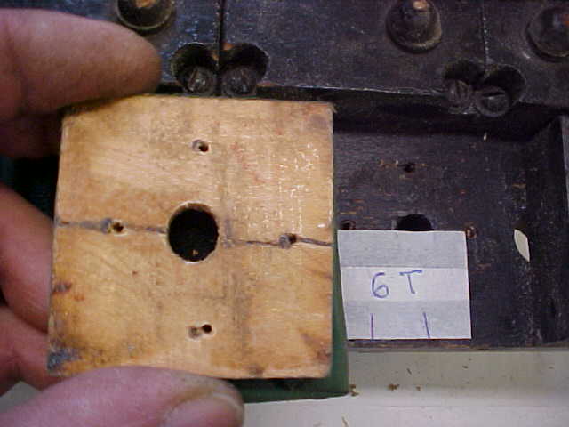
PHOTO D 8 Miss-marked intensity This is the result of a poorly marked intensity pneumatic. The screw holes are not consistent from one pneumatic to the next. If these pneumatics are miss-marked it will be impossible to get them back using the original screw holes. They will not line up straight on the base. In this case the wood split. I've run into this situation many times. There is a drawing (template) at the end of this writing showing the original location of the intensity pneumatics in case you have to make new ones. The instructions for using this template may be found at the end of this section beginning with photograph D 17. |
 |
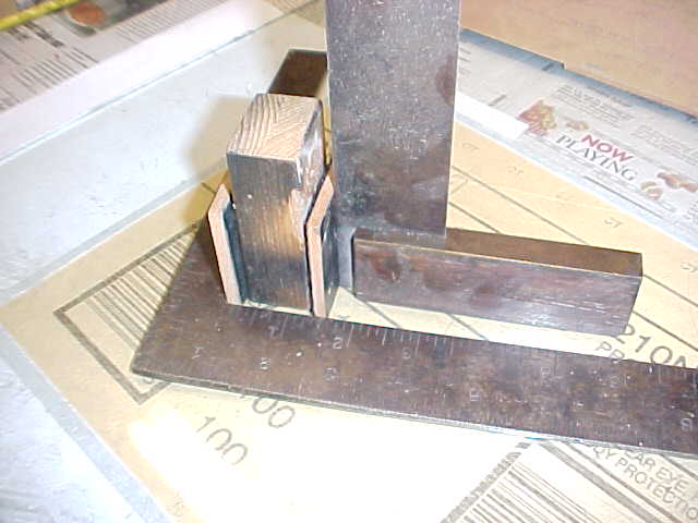 |
PHOTO D 9 First step to recover intensity pneumatic The next three photos (D 9 - D 11) show the steps to take to recover the intensity pneumatics. In this photo the pneumatic is squared in all directions. The pneumatic is resting on my resurfacing glass which I have flipped upside. Careful sanding, keeping everything square, will help in the recovering. The overlapping side is facing up. The wooden spacer measures one inch thick. The original measurement of the cloth on the intensity pneumatic is one and a half inches. I have a permanent, substantial jug for recovering these pneumatics (not shown) so they end up square. It is not practical to make a jig if you are just going to restore one piano and so pictured here is a simple spacer block one inch thick. I used a block like this along with "C" clamps for this process for many years with good results. |
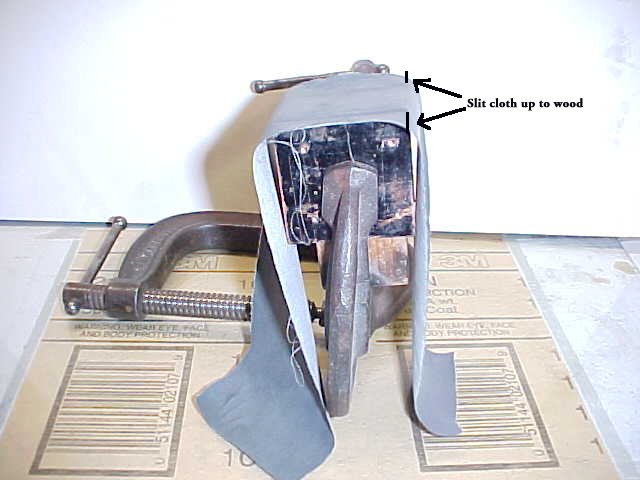 |
PHOTO D 10 Second step After squaring the intensity pneumatic put a "C" clamp on it taking care not to twist the boards out of square. The clamp should be firm but not tight. I always tear (rather than cut) key pneumatic cloth. Test the cloth by pulling it in both directions. The direction that pulls the least will run the length of the pneumatic. After the glue has set on the top side, slit the cloth in the corners. This will make it easier to cover the sides. |
|
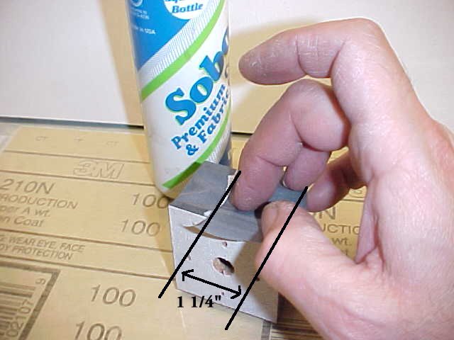
PHOTO D 11 Third step After three sides have been recovered it is time to recover the side with the overlap. Cut the cloth ends to one and a quarter inches on each side to end up with the proper overlap. I use Sobo to glue the overlap. Sobo is very pliable and adheres well to rubber cloth. If hot glue is used on the overlap that one side will be stiff. Press out any excess glue from the overlap. Clean excess glue from the cloth with a moist towel. A moist towel may be used to clean glue from any grade of cloth. The last step is to make a gasket for the bottom. In the photo the gasket has already been attached for purposes of demonstration. Use scraps of pouch leather for this gasket. Pouch leather is thinner than the original cork and so the four screws that hold the pneumatic onto the base will have a little more wood to grip onto. Glue the pouch leather gasket with the nap side out. Use as little glue as possible when attaching this or any other gasket. Do not make hills of glue on a piece of wood that you have just gone through the trouble to flatten out. Remember the gasket does the sealing not the glue. Brush a thin coating of flake shellac on the gasket before screwing it back to the base. The shellac will make a tight seal in case the wood shrinks due to a change in humidity. |
 |
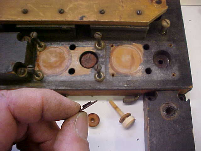 |
PHOTO D 12 Valve seats These fiber seats were used in various components of the Ampico. Always break fiber seats out and resurface them. Many of these seats were not glued in very well from the factory and are ready to fall out. In early expression mechanisms these seats are nickel-plated brass, so if you break a seat you can have a new one made out of brass. Resurface the new brass seats and coat them with brass lacquer spray. On early seats the nickel will be sanded off during resurfacing and so they too must be sprayed with brass lacquer. These seats are not porous so glue them back in place with Sobo glue. The primary type valve has been taken apart. It is on the bottom, center of the photo. The leather punching on the valve stem is no longer snug on the stem. This will allow air to seep around the stem and cause a small loss of vacuum. When making a replacement for this leather make sure the center hole is snug to the valve stem. When replacing this leather, be careful to match the original thickness. Changing the thickness will raise or lower the valve in relation to the pouch. The distance from the bottom of the valve to the top of the pouch should not be changed. The top buttons on these primary type valves must also be resurfaced. Scrape all the old glue from the crest of this button. This will insure the fresh hot glue will adhere to clean wood. If the cap is not scraped the fresh hot glue may peel up. Sometimes these buttons were not drilled perpendicularly to the flat surface. Buttons that were not drilled correctly should be discarded. It is a good idea to order a dozen buttons from Bob Streicher when you order replacement parts. |
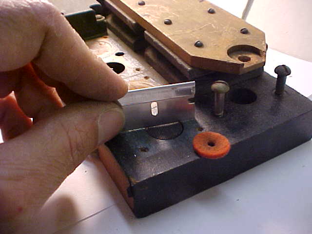 |
PHOTO D 13 Setting the intensity valves The locking valves located in the wells should be broken down. Resurface the center core of these valves and cover the bottom of each locking valve with kidskin, nap side showing. Put the re-leathered valve in the well and lay the felt punching that acts as it's top seat on top of the valve. Next, place a punching thirty five thousandths thick on top of the felt (I use a punching of Stayfast cloth for this). Place a straight edge on top of the well and see if there is a gap between the punching and the straight edge. If there is, glue half-inch diameter punchings made from very thin pouch leather on the top side of the locking valve. Leave a slight gap between the punching and the straight edge as shown in the photo. The new leather gasket on the valve block will compress except in the area of the well so a slight gap will allow for this. This method of setting valve travel can be used for the amplifier valve as well as the crescendos. In the case of the crescendos and the amplifier, the valve heights should be set level with the straight edge since the gaskets for the top seats of these valves do not compress as much due to their larger surface areas. |
|
PHOTO D 14 Making complex gaskets. Replace the cork gasket on these valve blocks with leather. The leather should be about thirty five to forty thousandths thick. I buy upholstery leather used in antique car restorations from Bill Hirsh. To save money, ask Bill if he has a remnant for sale or a discontinued color that can be purchased at a discount. I have placed a newspaper punching in the well to keep paint from getting in the well. I sprayed black paint on the bottom of the valve block and then I quickly pressed the block onto the leather before the paint had a chance to dry. This method makes it possible to make perfect gaskets without having to mar the wood with an Exacto knife. I developed this method years ago after rebuilding many double valve Standard primary chests. Each of these blocks are held down with four screws. The base of the expression unit to which these blocks are screwed is made from red gum wood. This is the same wood that was used in making the distributor base as discussed in section A. Just as the distributor base board screw holes often strip out, the valve block screws in the expression mechanism will also strip occasionally. To secure the screw holes, apply a few drops of instant glue in each of the four screw holes in the base. The instant glue will be absorbed into the wood to harden the wood fibers in the screw holes. The instant glue should be left to dry overnight. As a precaution, apply some soap to the threads of the screws before installing them to guard against screws being accidentally glued in place. |
 |
|
SETTING UP THE EXPRESSION AFTER RESTORATION After each expression mechanism has been reassembled, it is essential that you set the height of the top lever. This is the maple lever that has the tops of the three intensity pneumatics screwed to it. Push down on the lever and adjust the new plastic nut and the brass thumb-nut until the lever is parallel to the main base. If you are working on an early expression unit that does not have brass thumb-nuts make new ones. The nuts have a knurled edge, they are one eighth of an inch thick and are three eighths of an inch in diameter. The nuts are tapped with a four-forty tap. Use plastic nuts instead of leather because leather will corrode the threaded rod. On the bottom of each expression mechanism, set the stop collar on the valve stem so there is three sixteenths of an inch space between the cloth punching above the stop collar and the bottom of the valve stem bushing guide. Do not set it any higher. If anything, set it just a little less than three sixteenths of an inch. To set the zero intensity, move the plastic nuts and metal thumb nut on the spring pneumatics. Lower the nuts (open the pneumatic wider) to make the zero setting louder, raise the nuts (close the pneumatic) to make it softer. Do not use the crescendo springs to regulate the zero intensity. Set the crescendo bolts by centering them on the casting. Only change the spring tension on the crescendos to change the curve of the crescendo expression. If one of the crescendo springs has been stretched by a previous restorer you must replace it with an original spring. By following the steps in the Inspector's Reference Book, it is possible to set up an Ampico in less then an hour. If you would like to have the zero setting softer but you find that notes drop out on soft passages you must regulate your piano action to a finer degree. A well-restored Ampico will have the ability to play softly without dropping notes. |
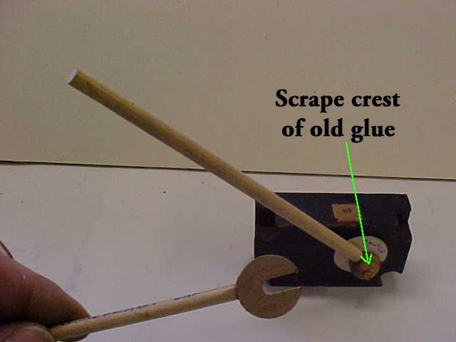 |
PHOTO D 15 Setting primary gaps This is a very simple tool to make and it works very well. Glue the following two front rail punchings together: a twenty five thousandths thick punching and a five thousandths thick punching. Use as little glue as possible to glue them together. Take a hammer shank and sand a flat spot on the edge of one side. Glue the punching you have made to the flat spot and then cut a notch in the punching. Put the primary valve block on its side with the gapping tool under the top button. Hold the tool at a forty-five degree angle. If hammer shank does not fall the valve gap is too close. Open the gap up a little and try again. If the hammer shank falls quickly in the eleven o'clock position then the gap is too wide. You can set all the primary valves on the primary chest in this same manner. This method will give proper travel to most types of primary valves including Standard and Deluxe. When the gap is set, brush a very small amount of hot glue on top of the cap to glue the dowel in place. After this glue has set, brush a thin coat of hot glue on the crest of the cap to seal the end grain. |
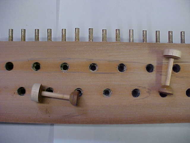 |
PHOTO D 16 Sanding the primary chest When restoring the primary chest, always sand both surfaces of the top board. Depressions in this board have been outlined to demonstrate the necessity for block sanding. Use very fine paper when sanding this board. Coarse paper will scratch the board and cause leaks. Make sure the sanding block is flat. Start with 120 grit paper and finish up with 220. Give a final pass with dulled 320. Then rub talcum powder into both sides of the wood to fill in the pores. The factory sealed this board with a wash coat of shellac but I choose not to do this. |
|
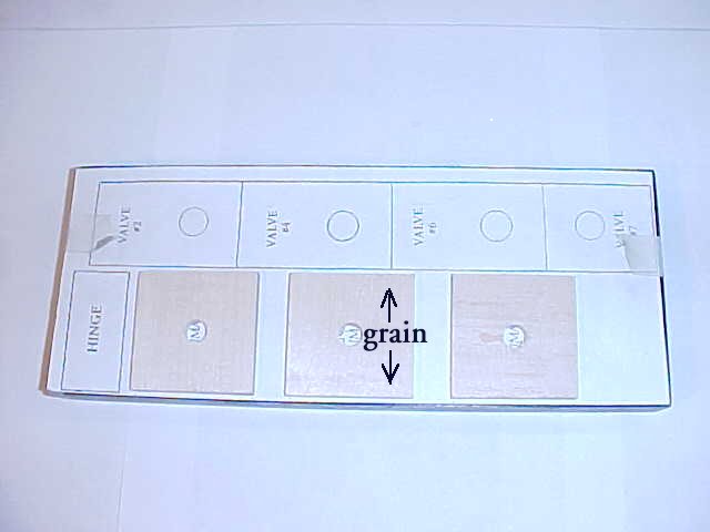
PHOTO D 17 Using the template A mirror image of the template can be made on a color copy machine at Staples. Trim the template and place it on the expression deck. Cut two oversize holes for the two screws that secure the hinge block. Screw on the hinge block and align it with the rectangle on the template then tape the template in place keeping the outlines of the expression pneumatics parallel with the edge of the board. Place the new pneumatic board over the impression on the template. As the board is being held in place, use an awl to mark the locations of the screw holes. Remove the board and mark the underside as in photo D 7. Do not forget to mark the two lines indicating the side of the pneumatic with the cloth overlap. Drill pilot holes for the screws in the bottom of the new boards and screw them in place. |
 |
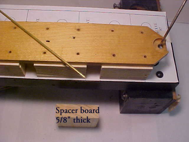 |
PHOTO D 18 Using the template When cutting new boards for the expression pneumatics, cut three boards to the same size square using 5/8" thick wood. Screw the expression board to the main body of the expression mechanism as shown in the right side of this photo. Put the expression rod through the bushings in the main body of the expression. Use the spacer blocks to line up the new top boards with the new bottoms. After replacing the hinge material, put the lever board in place but do not attach it. Make sure the lever board remains parallel to the front of the base board. Find a position for the lever board where the expression rod does not rub on the sides of the hole that it passes through. As you can see in this photo, the rod does not have to be centered in the hole, just make sure there is some clearance. Next, attach the hinge to the hinge block using the four screws and the retaining bar. In the center of the photo you can see a brass rod that has been sharpened to a point. I used this to mark for the new screw holes. After the screw holes have been marked, remove the lever board and mark the tops of each pneumatic as in section D 7. The interiors of the new expression pneumatics are now ready to be lined with felt. Felt is often used inside pneumatics to quiet air noises. Use the hammer file to bevel the edges of the new felt as it was originally. |
|
on November 10, 2022 by John A. Tuttle, who Assumes No Liability For The Accuracy or Validity of the Statements and/or Opinions Expressed within the Pages of the Player-Care Domain. This page was last revised on December 18, 2024. |
|
407 19th Ave, Brick, NJ, 08724 Phone Number 732-840-8787 (Voicemail Only, No Texts) |
